Bessey Clamp Racks With Epoxy Logos
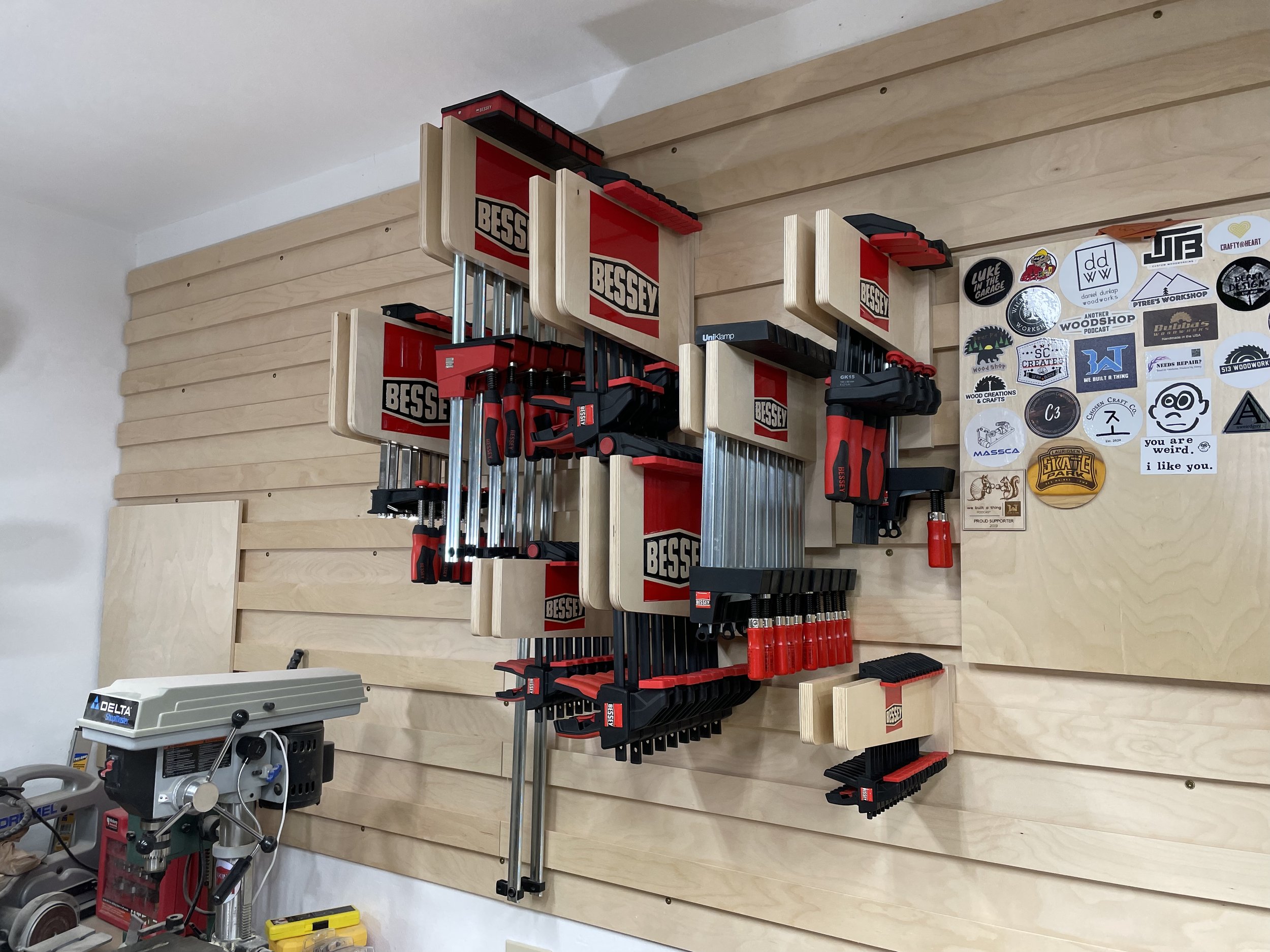
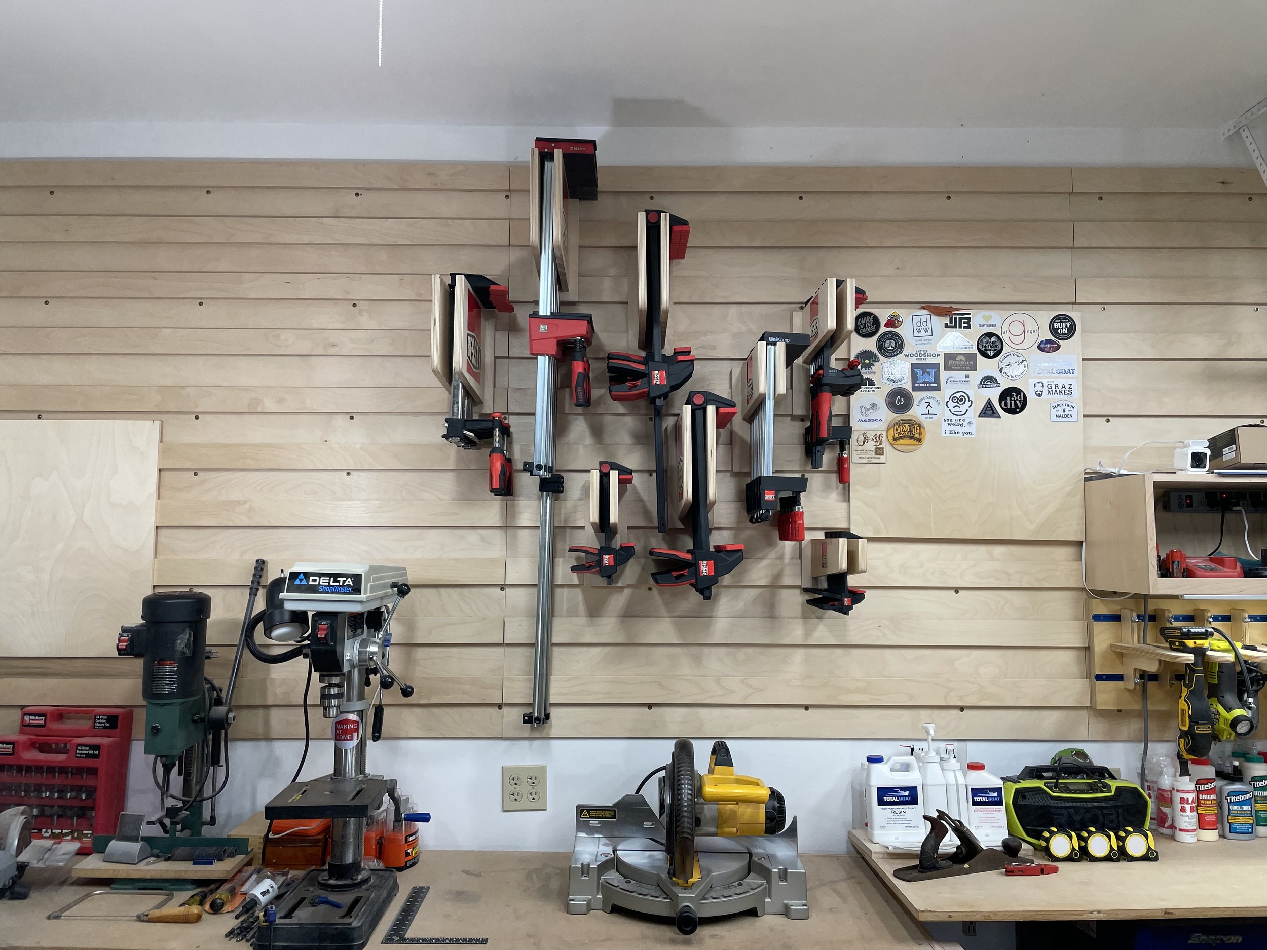
In this project I am going to show you how to create clamp racks for Bessey Tools clamps of various sizes. I'll show you how I carved the Bessey logo into the sides of the clamp racks and then filled with red and black epoxy to match the logo.
I have been needing to organize my work area in the garage for some time and I recently purchased some Bessey Tool clamps for woodworking projects as well as getting some through a giveaway. I thought it would be best to get the clamps organized and in a place a can access them fast and grab the right ones I need at the time. I thought it would be fun to carve the Bessey Tools logo into the sides of the clamp racks I made for the cleat storage wall.
Step 1: Tools, Software and Materials
SOFTWARE
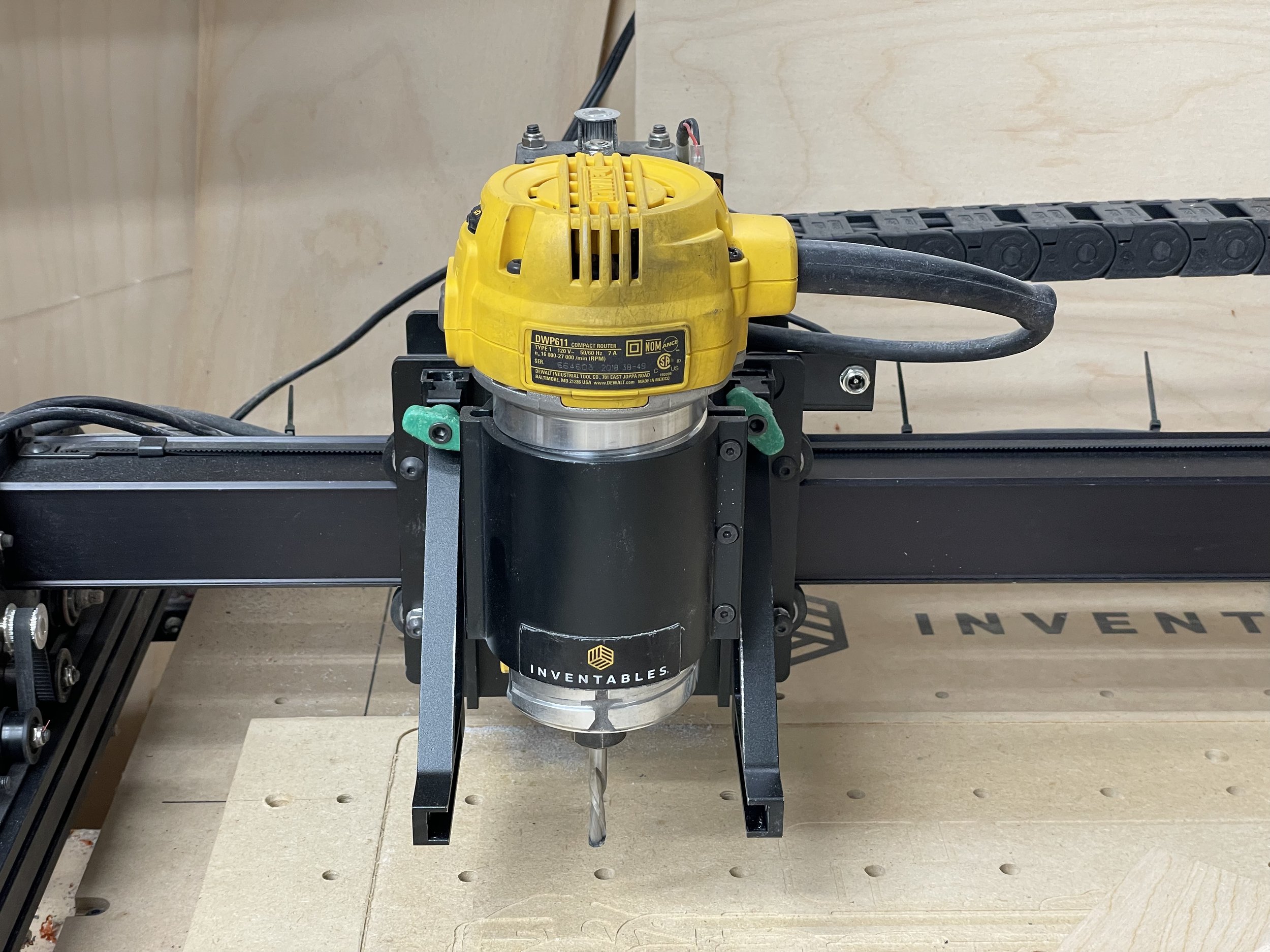
Easel Pro Software by Inventables - https://www.inventables.com/technologies/easel?ref=MakingAtHome
The tools I used on the project were as follows:
TOOLS
X-Carve 1000mm CNC Machine by Inventables - https://www.inventables.com/technologies/x-carve?ref=MakingAtHome
Router Bit - 1/8" Fishtail Spiral Downcut Bit - https://www.inventables.com/technologies/solid-carbide-fish-tail-downcut-spiral-bit-1-8-in-d?ref=MakingAtHome
Router Bit - 1/16" Fishtail Spiral Downcut Bit - https://www.inventables.com/technologies/solid-carbide-fish-tail-downcut-spiral-bit-1-16-in-d?ref=MakingAtHome
Router Bit - 1/32" Fishtail Spiral Downcut Bit - https://www.inventables.com/technologies/solid-carbide-fish-tail-downcut-spiral-bit-1-32-in-d?ref=MakingAtHome
Router Bit - 1/4" Downcut Bit
Random orbit sander
Shop vac
Drill
Drill Press
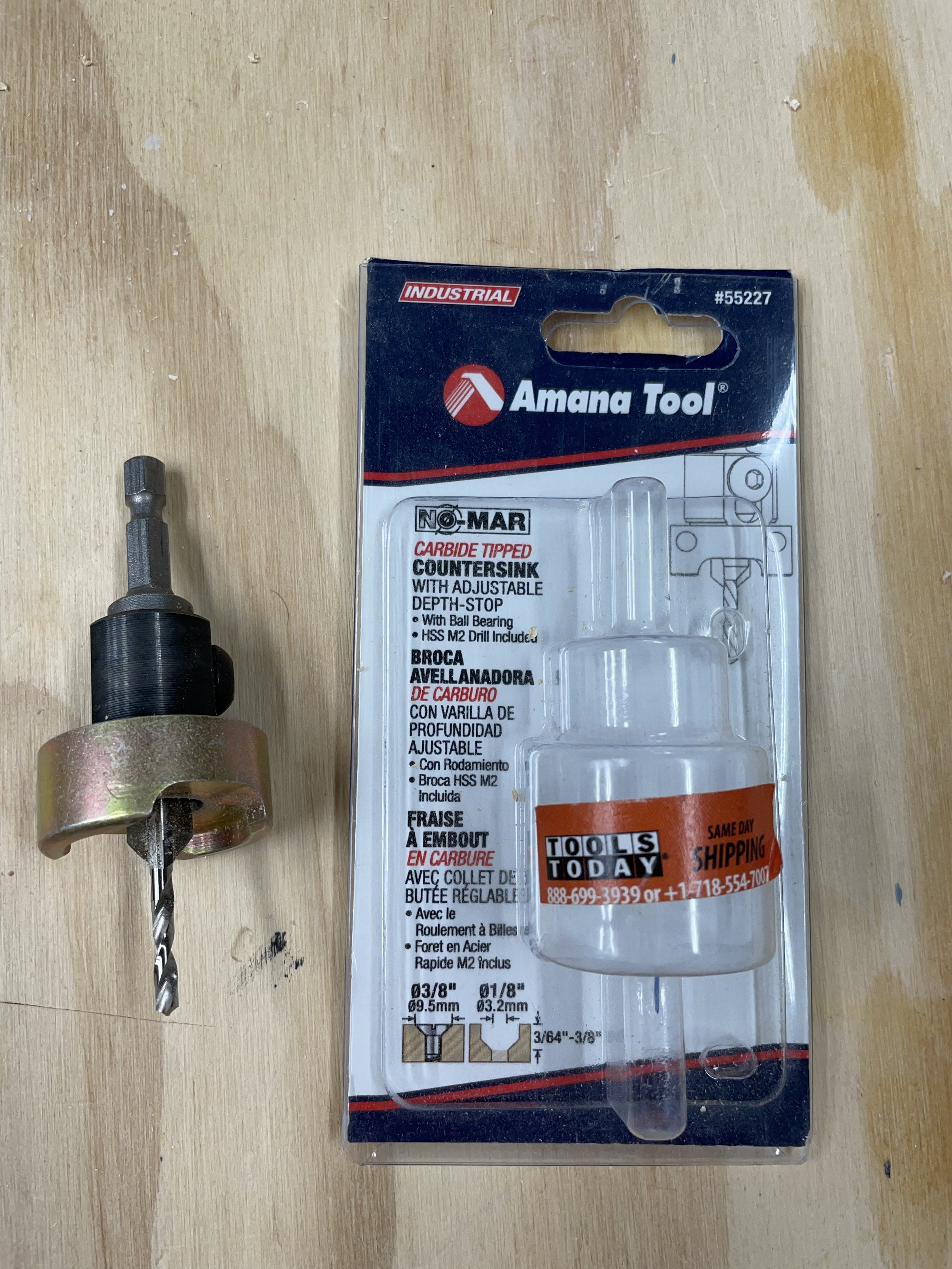
Amana Countersink Bit with Depth Stop #55227 - https://amzn.to/3jG58Ju
9/64" drill bit
Tape Measures (my favorite two):
Fastcap PMS-16 Auto Lock ProCarpenter Tape Measure - https://amzn.to/333fTMN
or FastCap PSSR16 16 ft Standard Reverse Measuring Tape - https://amzn.to/35eQe6k
Propane torch (to pop epoxy bubbles)
Bessey Clamps on the Clamp Racks
12 of Bessey UniKlamp Clamp, 12-Inch - UK3.012 - https://amzn.to/3Bq2RrE
4 of Bessey K-Body Revo Clamp, 24-Inch - https://amzn.to/3GF9CKj
2 of Bessey K-Body Revo Clamp, 50-Inch - https://amzn.to/3GsB65y
4 of Bessey One Hand Trigger Clamps, 24-Inch - EHKL24 - https://amzn.to/3EnF5yp
12 of Bessey One Hand Trigger Clamps, 12-Inch - EHKL12 - https://amzn.to/3Bkbbcn
8 of Bessey One Hand Trigger Clamps, 6-Inch - EHKM06 - https://amzn.to/3pLdy6a
12 of Bessey One Hand Trigger Clamps, 4.5-Inch - EHKMICRO - https://amzn.to/3CzeIF6
2 of Bessey Gear Clamps - GK15 - https://amzn.to/3jM4WrZ
2 of Bessey Gear Clamps - GK30 - https://amzn.to/3blu4kR
MATERIALS
3/4" Baltic Birch plywood.
Various sand paper
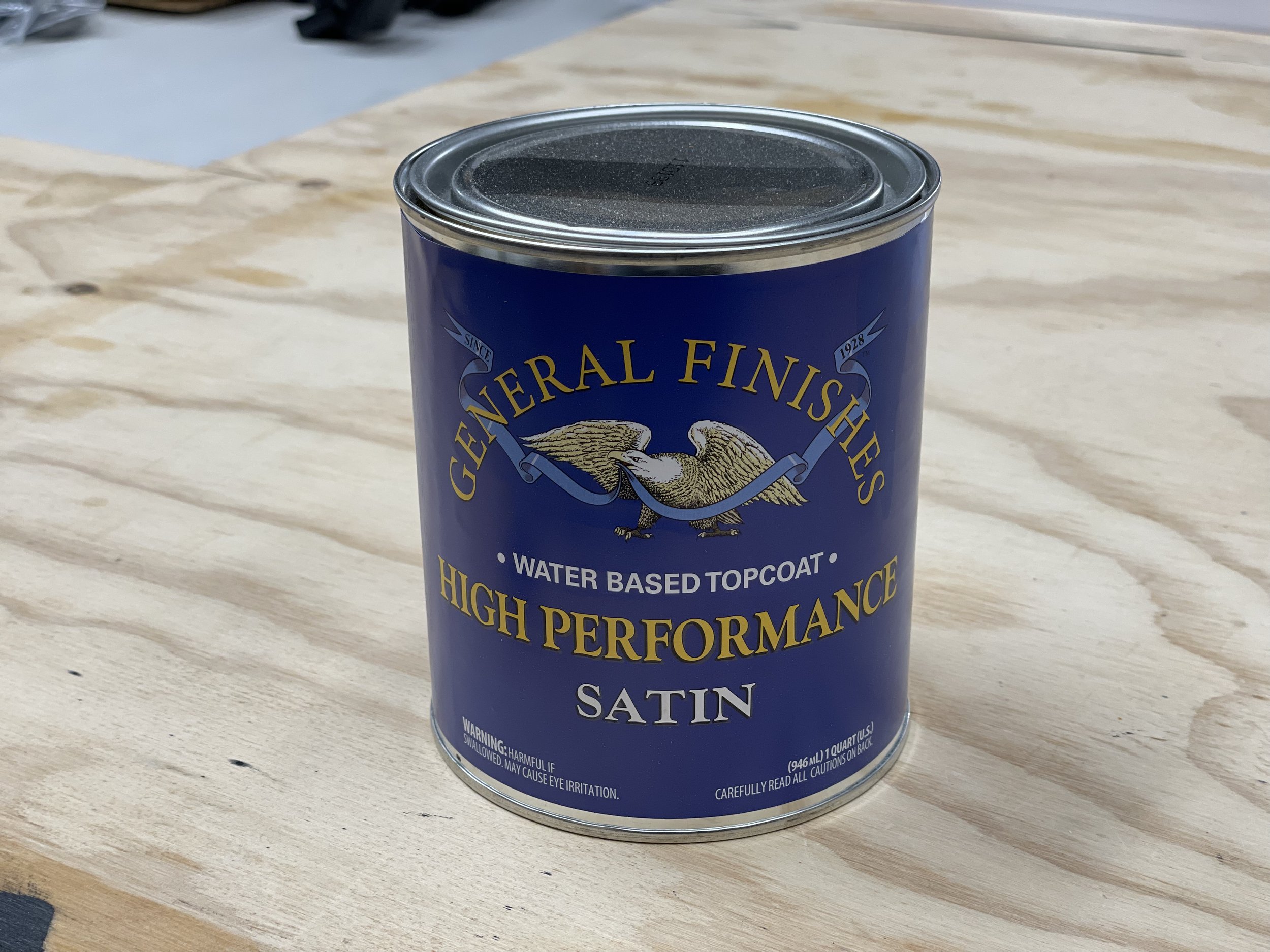
General Finishes Water Based Topcoat (Satin) - https://amzn.to/3Ep8lVG
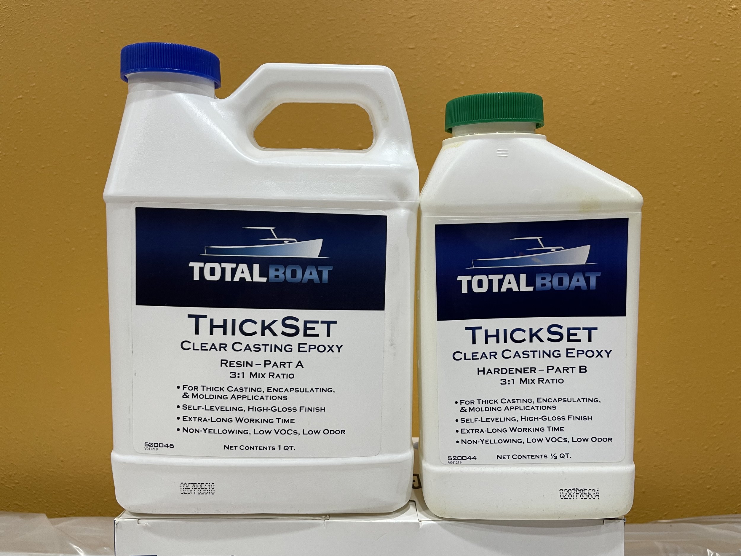
Total Boat Thick Set Epoxy 1.3 Quart Kit - https://amzn.to/3jK8DON
or Total Boat High Performance Epoxy 1 Quart Kit (medium set speed) - https://amzn.to/3aITVD0
Mixol Universal Tint - True Red #27 - https://amzn.to/2XPsFzI
Mixol Universal Tint - Black #1 - https://amzn.to/3CpvPJs
3" long #8 construction screws
NOTE: As an Amazon Associate I earn from qualifying purchases.
Other affiliate links may be used on this page, but do not affect pricing of the items.
NOTE: If you plan on using any tool for a project please make sure you are familiar with the tool and all of the dangers associated with it. If you are not familiar with a tool then you should ask someone who is to show you the proper way to use it. A lot of communities have classes at local colleges on the proper use of tools and machinery. There are also local woodworking clubs that offer classes at very reasonable rates for beginners. I highly recommend using these resources for your safety and for the most efficient use of the tool.
SAFETY FIRST
Always wear eye and hearing protection. Always work safe with the proper safety equipment and guards on your tools.
Step 2: Design of the Clamp Rack
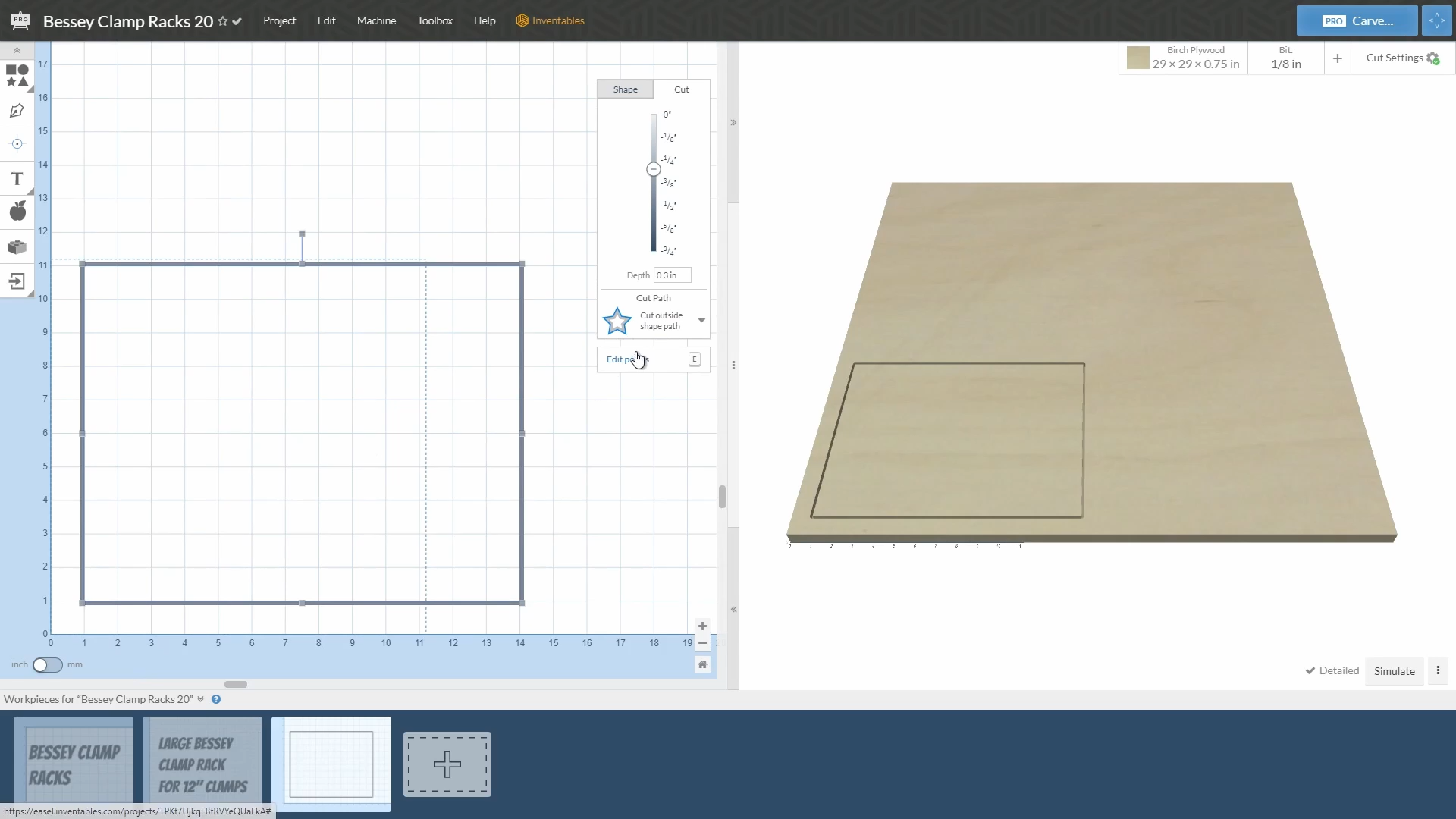
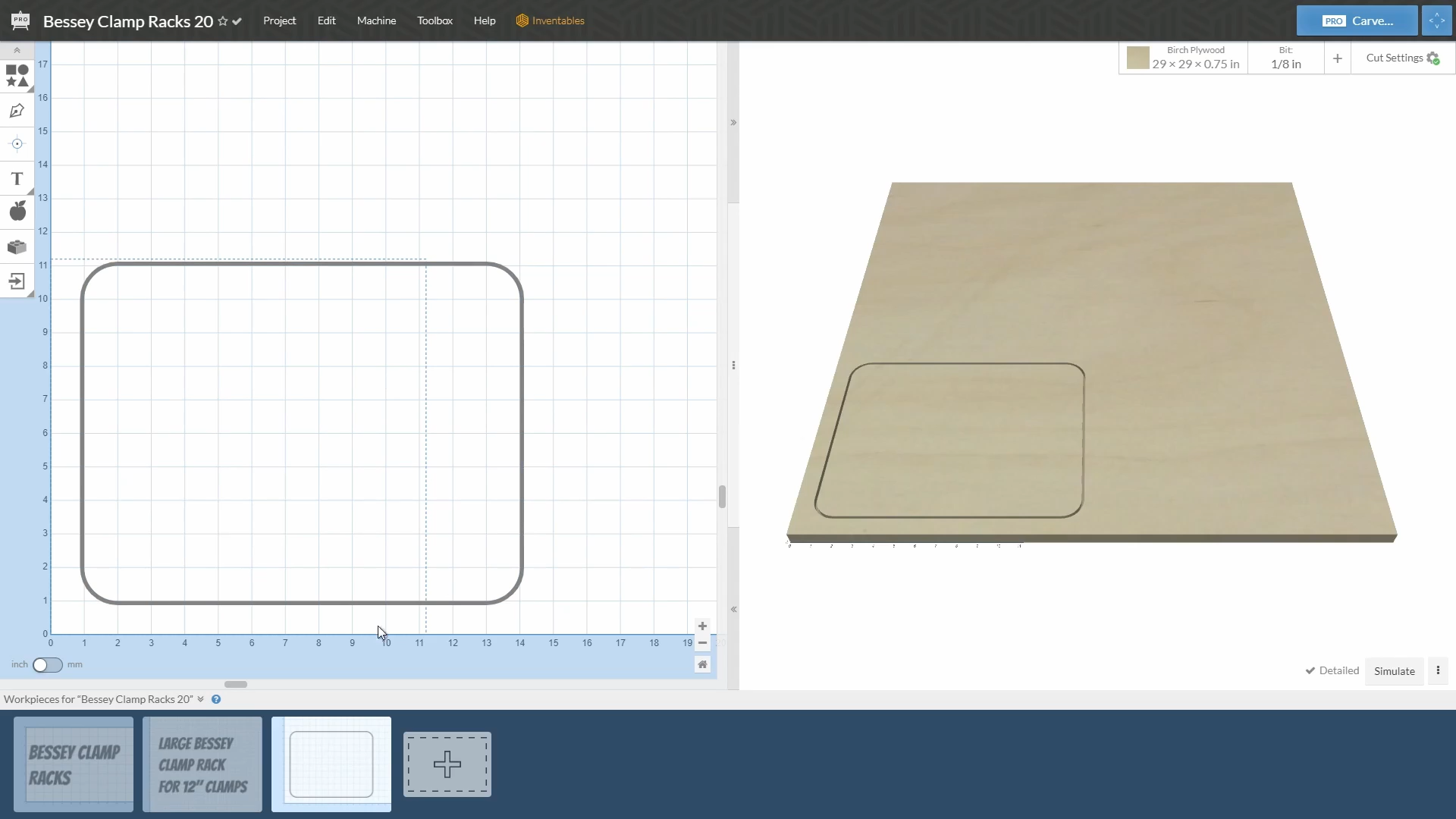
I wanted the clamp racks to be sized so they could hold a variety of clamps. I decided to build three different sizes of clamps. The sizes would be for 12" clamps and larger, for 6" clamps and larger, and 4-1/2" for the small clamps.
The racks are a design similar to what a lot of people build with two side plates. The clamps slide in between the plates. My clamp racks will have the Bessey logo carved into the side of the support plates. The logo will also have red and black epoxy paint in the carved logo.
I created the side plate of the largest of the clap racks by creating a 10" tall x 13" long rectangle.
I then rounded the corners with a 1" radius.
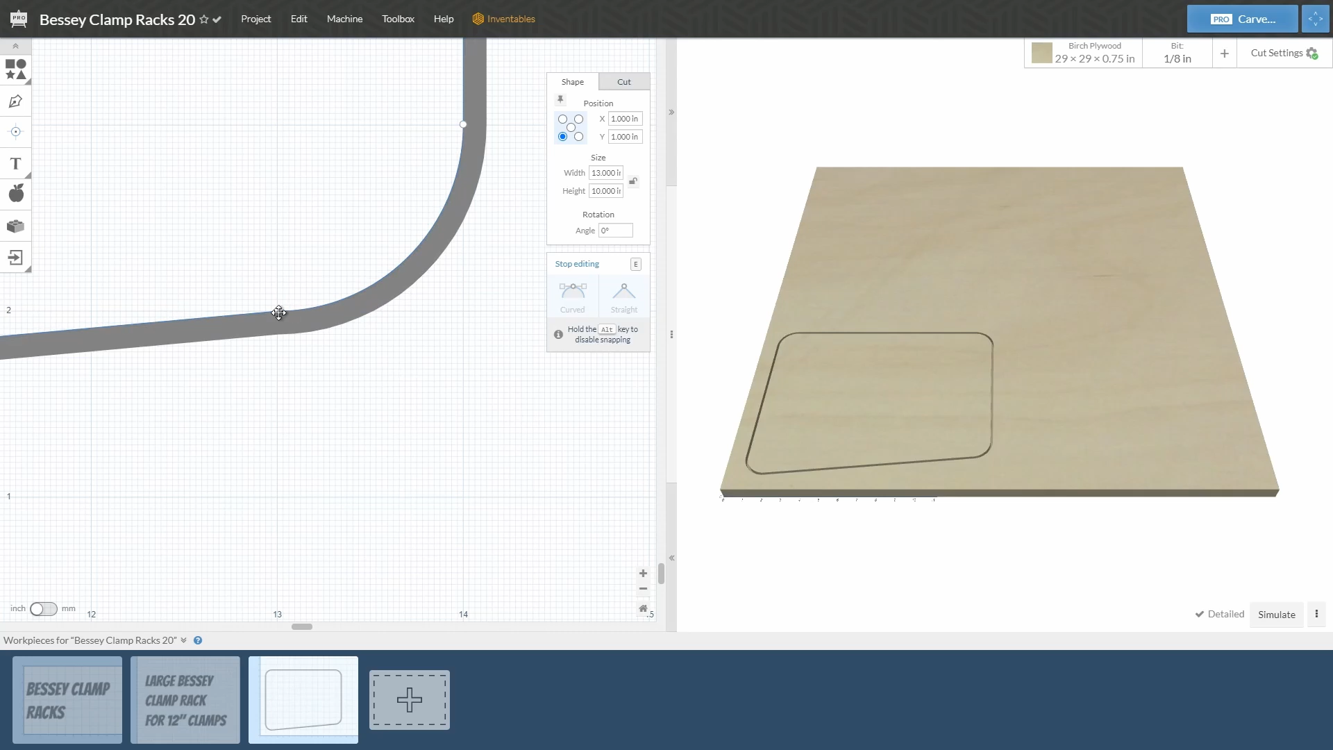
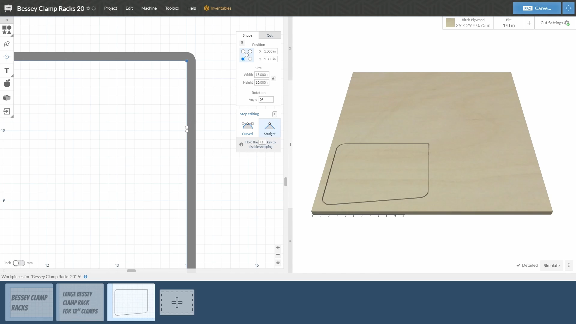
Next I removed the rounded corners on three of the corners by double clicking on the rectangle and then sliding one grip to the corner and deleting the other.
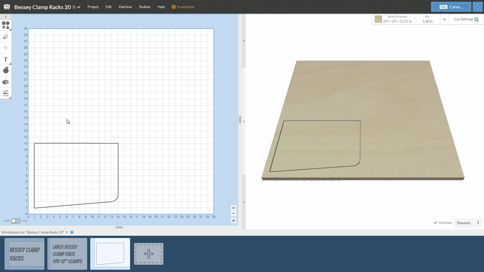
On the fourth corner (lower right) I slid the grips up 1" so the bottom of the rack plate would be tapered to the front which I thought would help with putting clamps on to the front. I then manipulated the grips for the radius to get a good transition for the radius.
Step 3: Importing the Logo
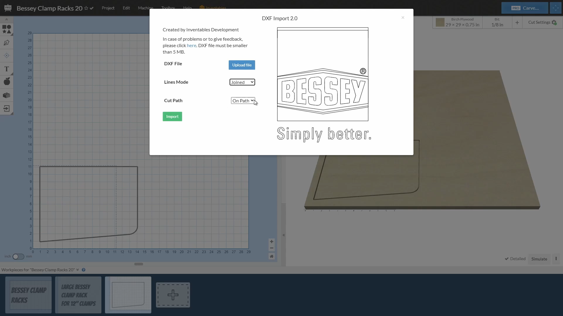
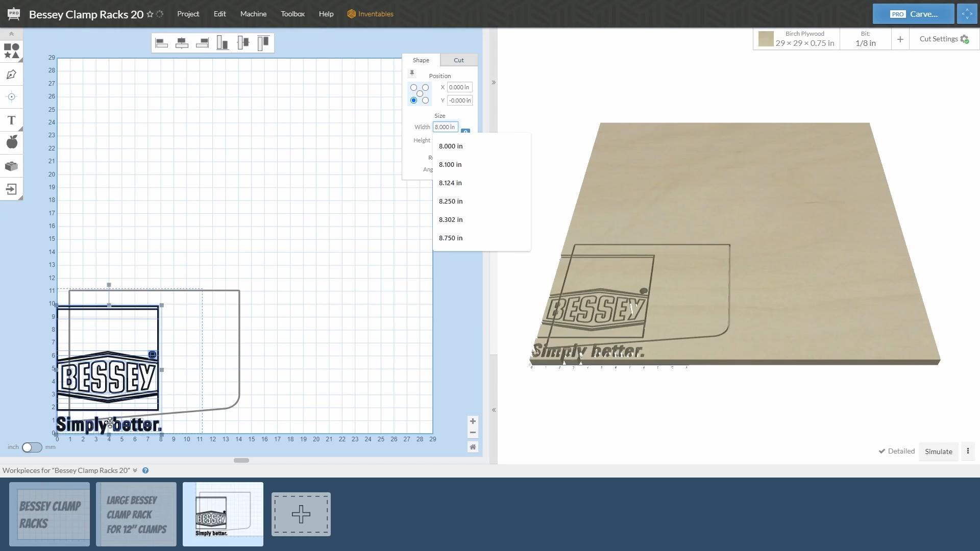
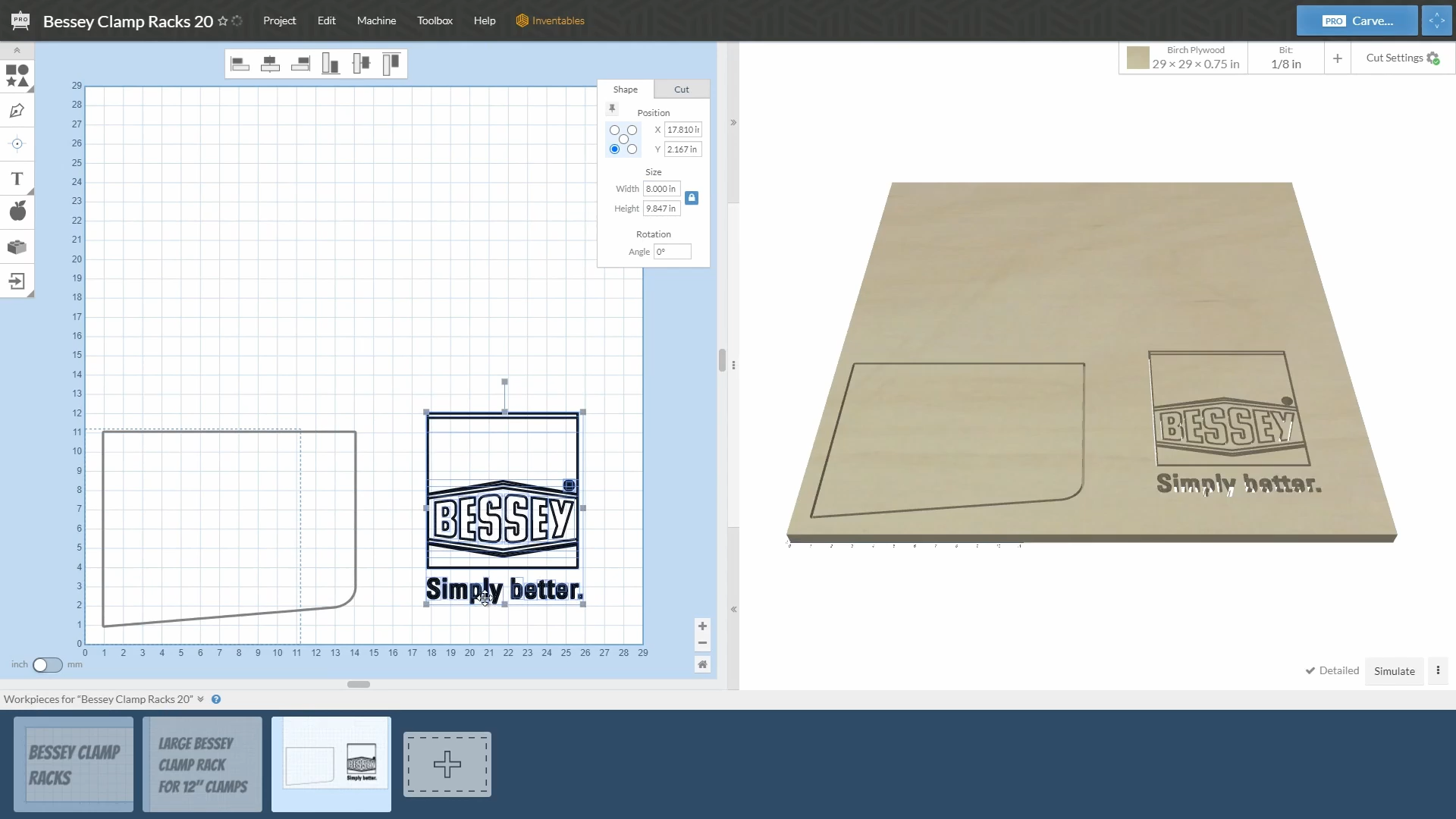
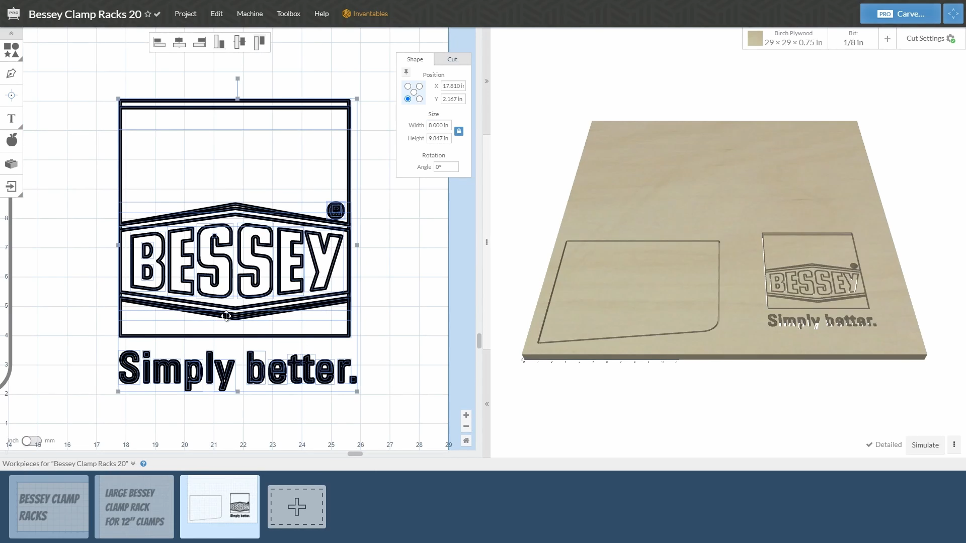

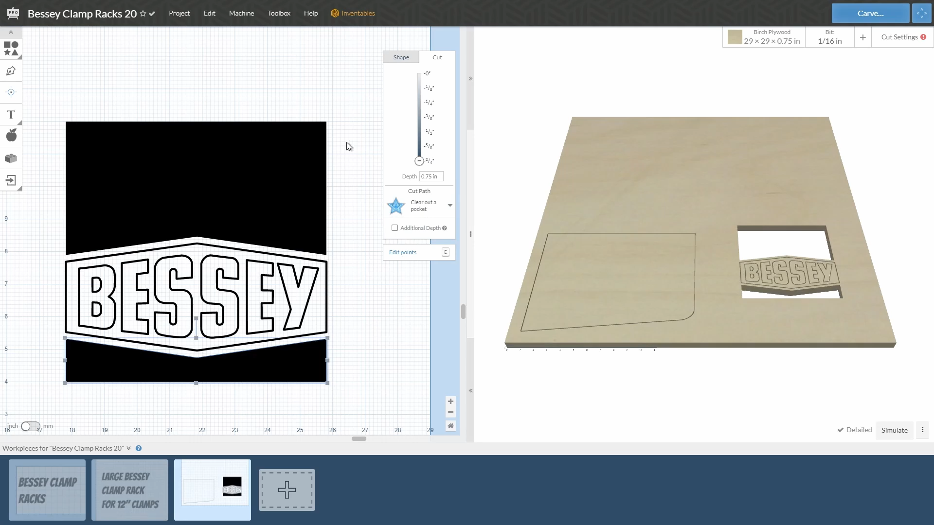
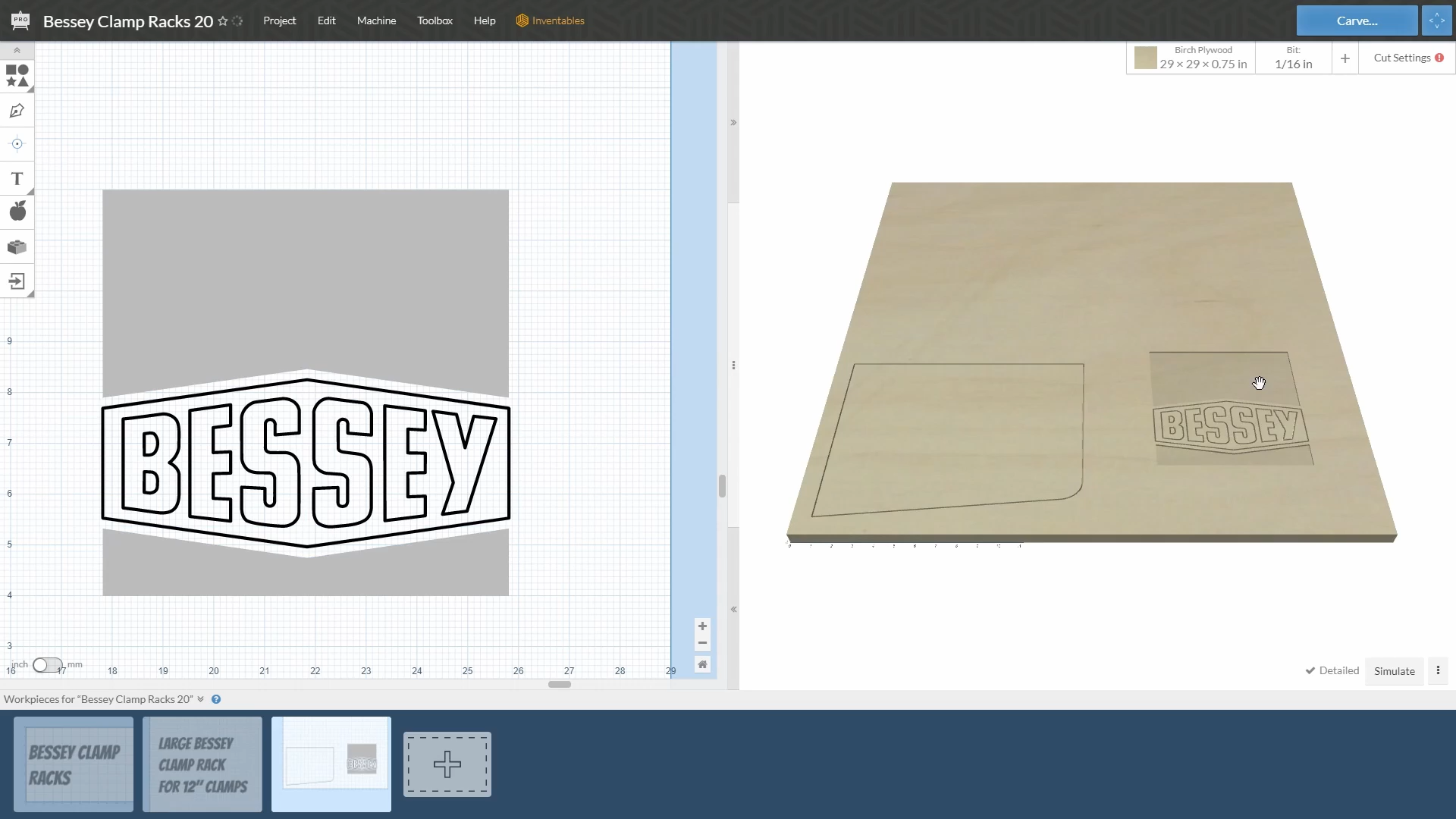
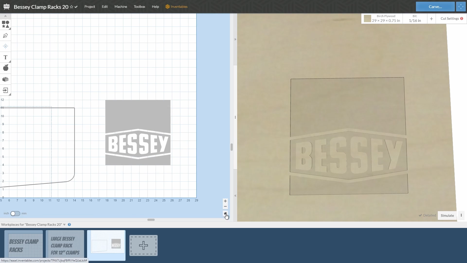
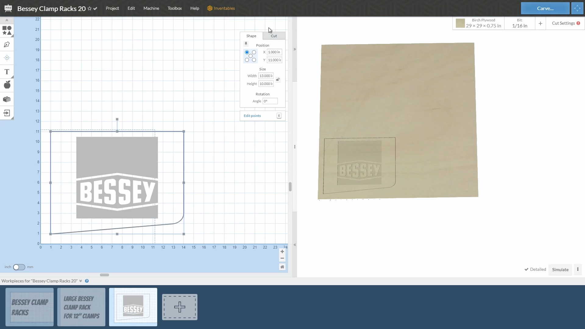
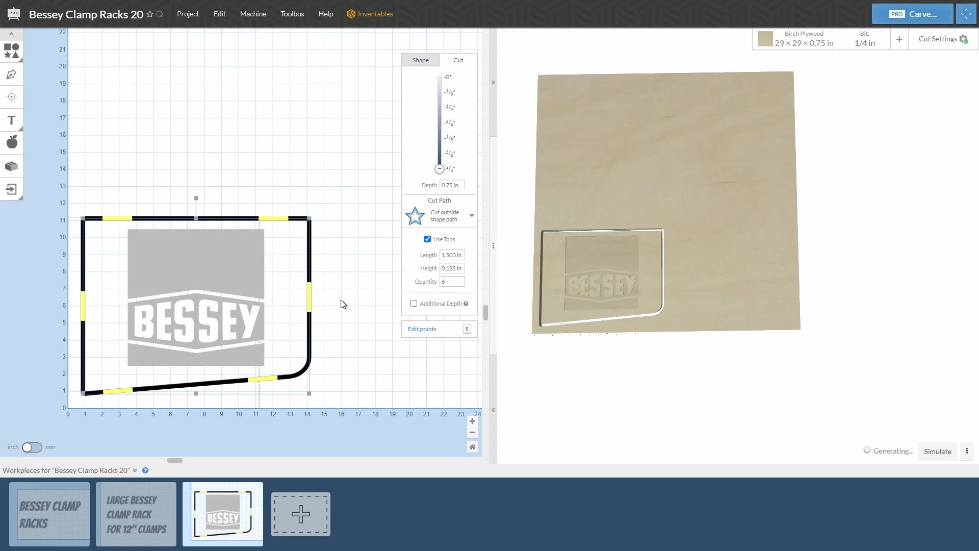
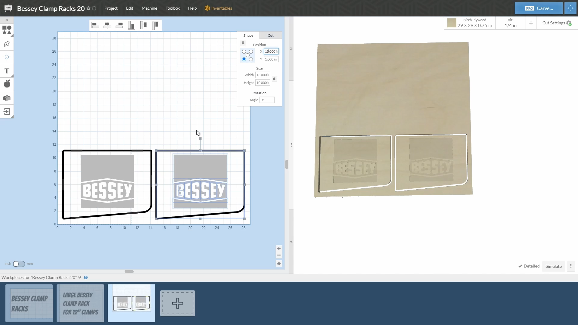
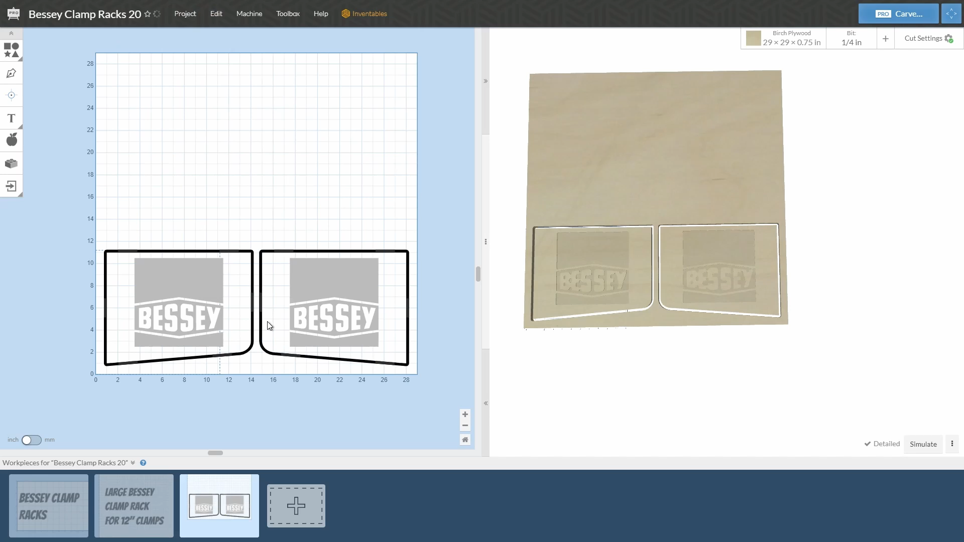
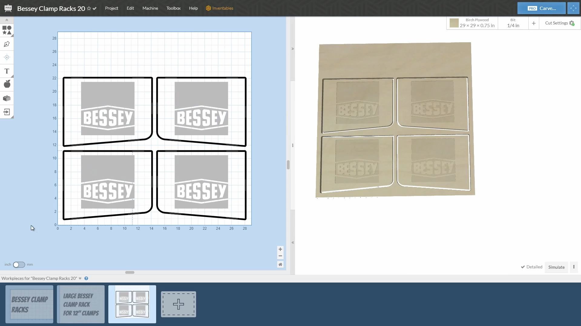
I was able to get the official Bessey logo files for the project and imported them into the Easel Pro software. To do this I imported a DXF file into the file through the import option.
Once imported you will need to "select all" and the scale the elements to the final size you want.
After scaling you will also need to set the carving depth for the elements. I modified the depth of the pocket areas to be 1/8". I set the outline cut with the 1/4" downcutting bit to be all the way through the material, but included tabs on the pieces so they would not come loose during carving and damage the bit or machine.
My plan for the logos was to carve the red and black areas and fill those with tinted epoxy. The white lettering would actually not be carved and would instead be a part of the face of the plywood.
Step 4: Carving
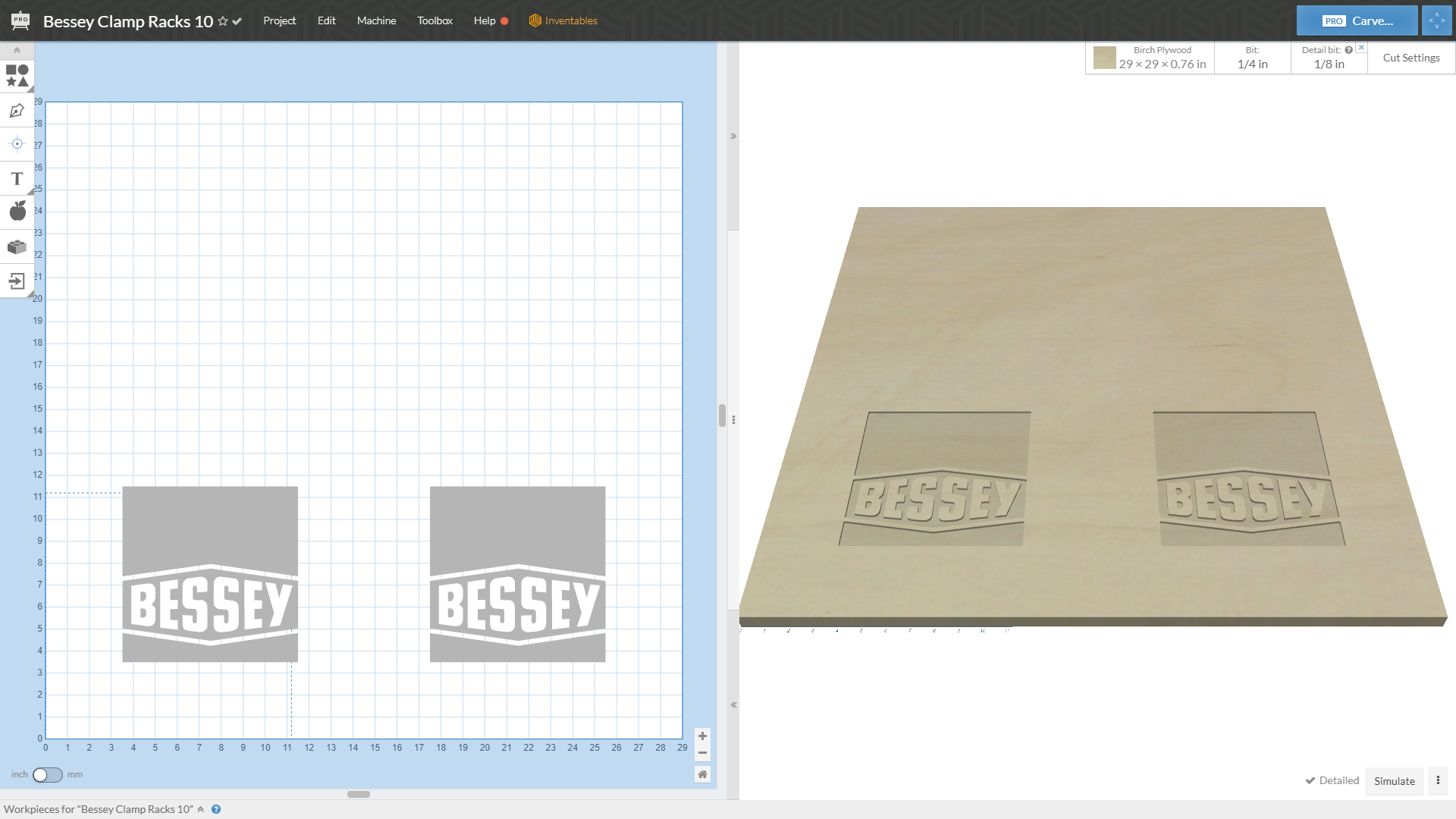
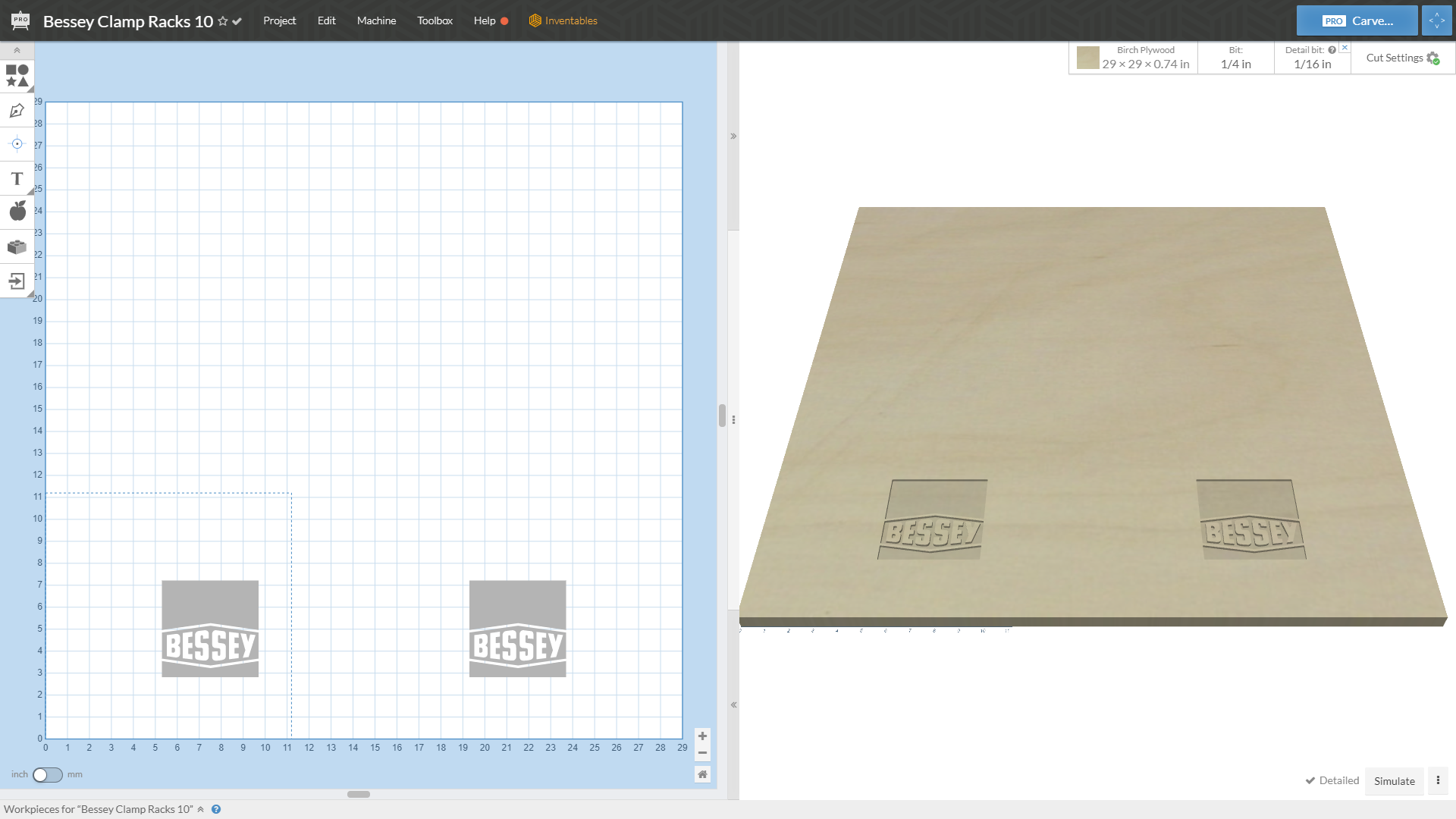
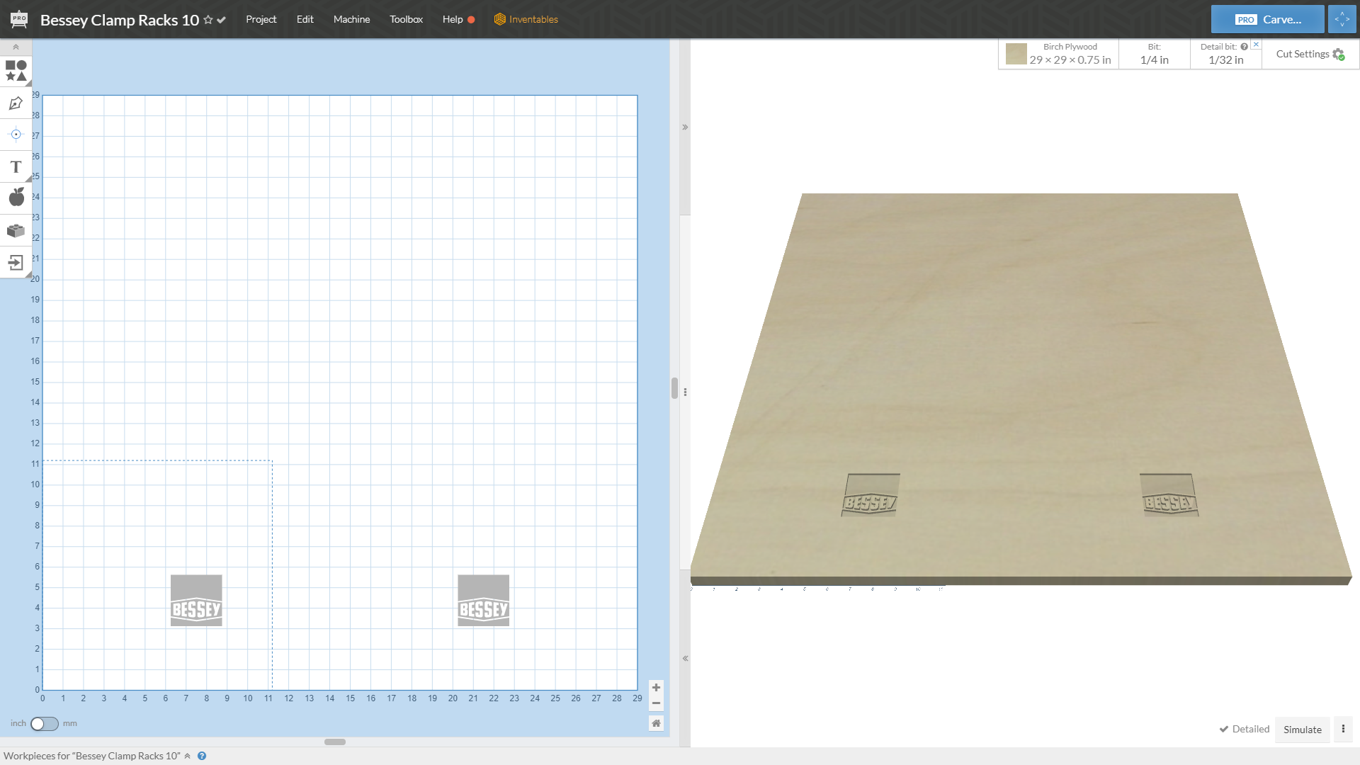
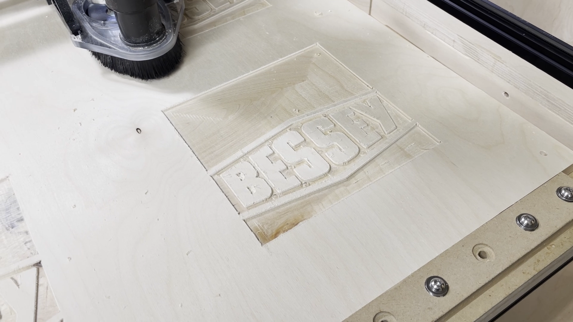
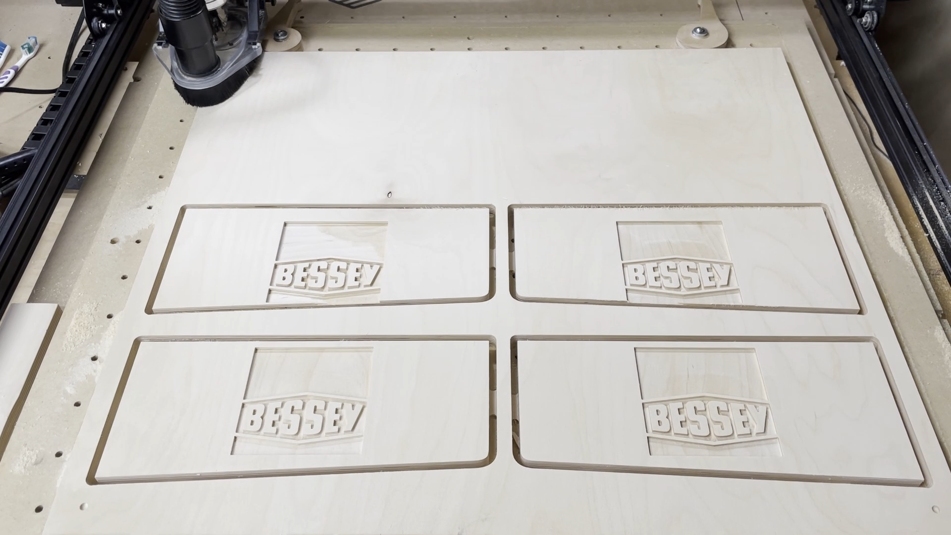
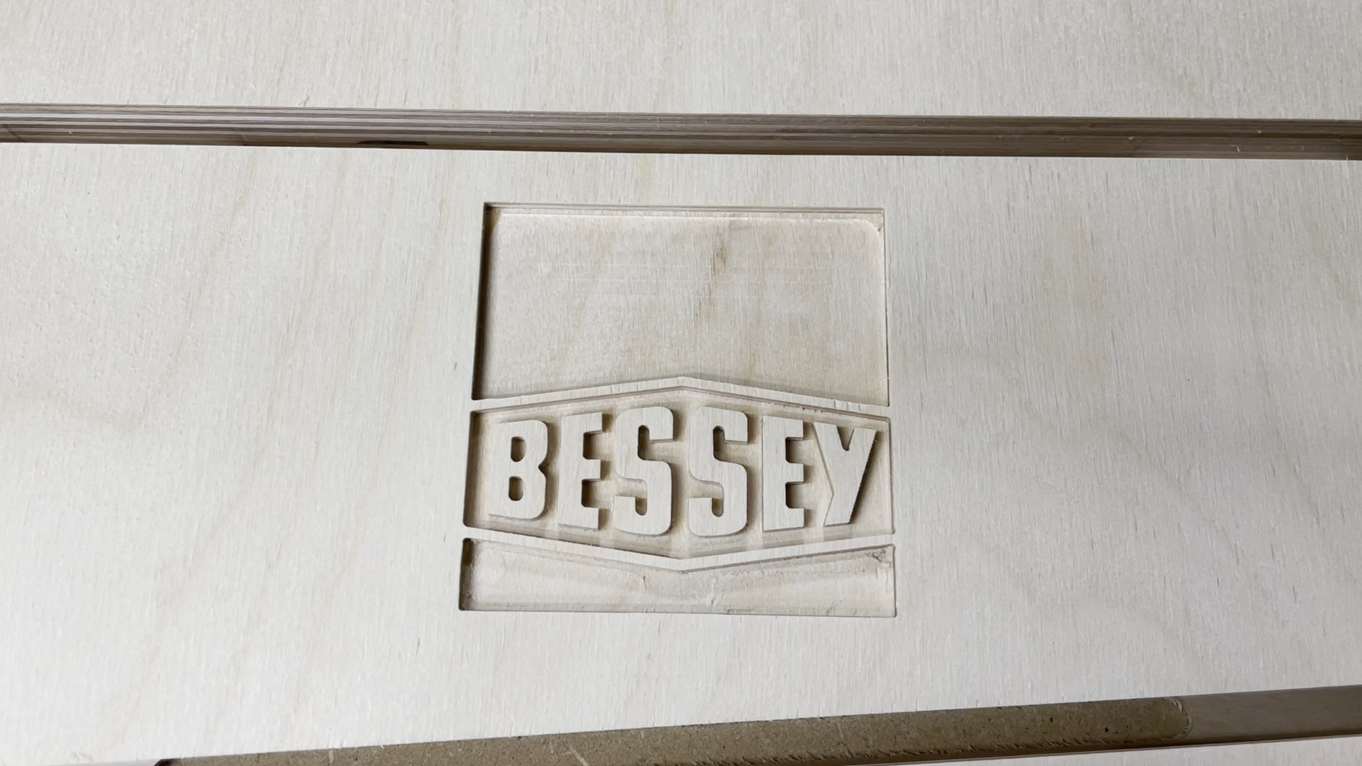
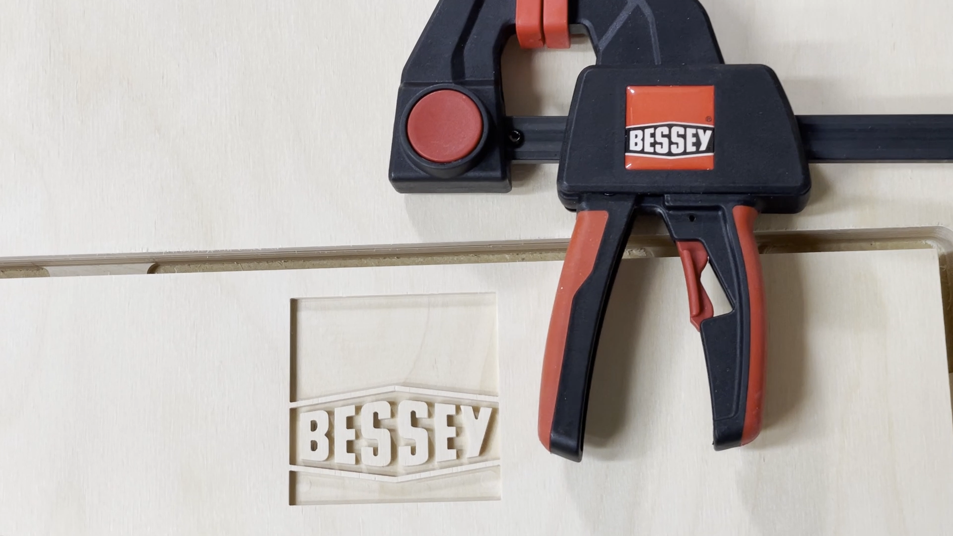
Carving the clamp rack side plates is done in several stages. First there is a roughing pass, then there is the detail pass, and finally there is the carve to cut the outline. See the table below for the clamp rack sizes and the sizes for the bits for each stage.
4.5" Rack
1/4" downcut bit (roughing)
1/32" downcut bit (detail bit)
6" Rack
1/4" downcut bit (roughing)
1/16" downcut bit (detail bit)
12" Rack
1/4" downcut bit (roughing)
1/8" downcut bit (detail bit)
All pieces were cut out with a 1/4" downcutting bit.
I used the default carving rates in the Inventables Easel Pro Software.
Step 5: Carving the Logos With a V-Bit
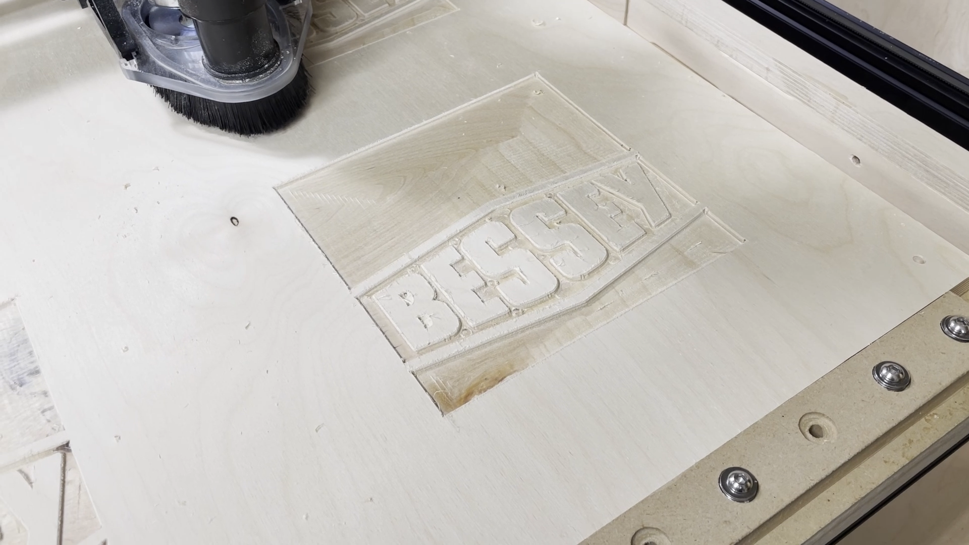
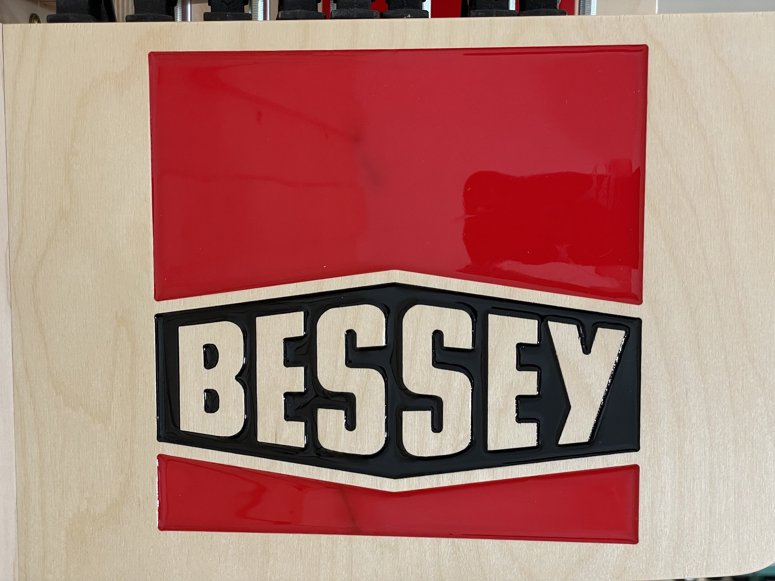
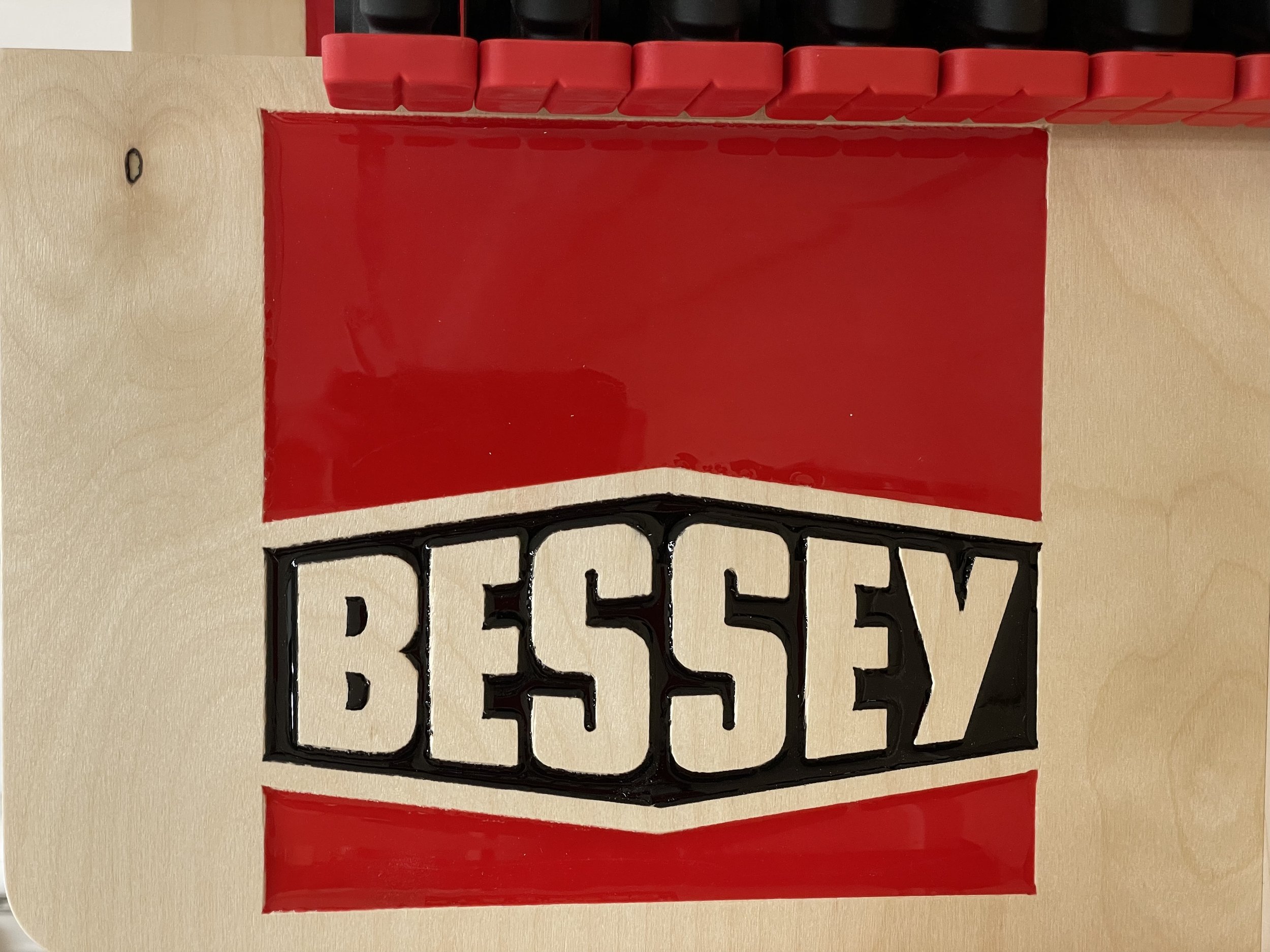
One of the things I wanted to compare on this projects was how the clamp racks looked when carving the logo with straight bits versus a 60 degree V-bit. The idea here was to see if the V-bit would carve the corners of the logo at a sharper point than the smaller round bits.
In the two pictures in this step you will see the difference between the straight bit carve and the v-bit carve.
I should mention that there was a little play in my z-axis that I noticed once the v-bit carve was completed. This was unfortunate, but still gave me a good comparison.
The v-bit carving still looks ok, but the issue really comes when pouring the epoxy. It is difficult to get consistent pour depths with the v-bit carving. If your epoxy is not up to the top surface of the lettering then you can see a portion of the exposed side of the carved area. This can make the lettering look wider if the epoxy is poured shallow or narrower if it is poured higher.
I decided the best and more consistent look for the rest of the clamp racks was to use straight bits for the racks where I would be pouring epoxy.
I think the V-bit carving of the logos would be good if you only wanted to carve the logos, but not fill with epoxy.
Step 6: Sanding and Finish
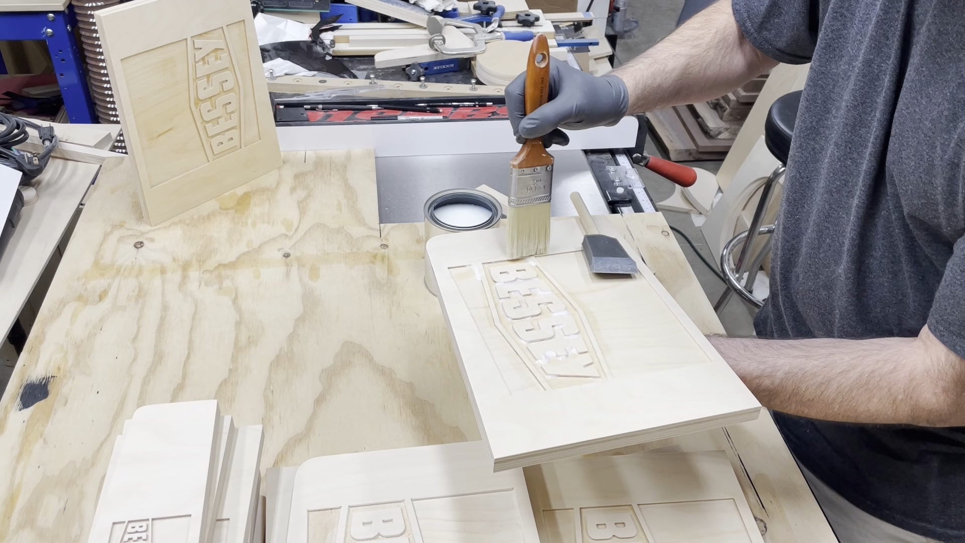
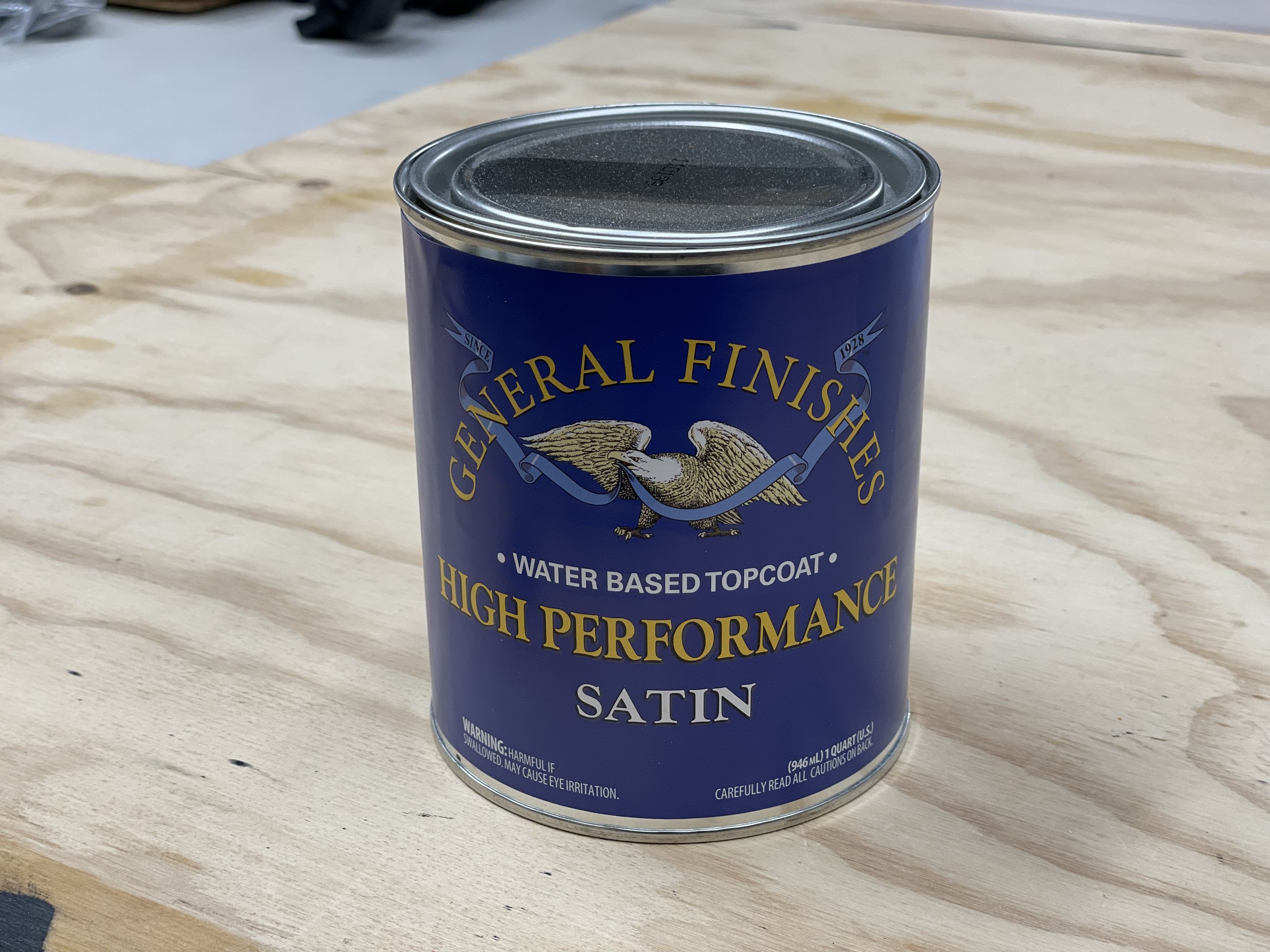
I sanded all of the faces of the plates to 180 grit so I could add finish to the pieces before adding the tinted epoxy to the logos. I used General Finishes water based topcoat High Performance Satin finish and applied two coats of finish with a light sanding between coats. Do not sand the areas inside the carved logos. You want this surface to be rough so the epoxy adheres well.
The idea here is to seal all of the pores/grain of the wood so you don't have tinted epoxy seep through the wood and discolor it outside of the carved logo area. Speaking from experience, a well flowing epoxy with tint can travel up to 2 inches into the wood through the side of the carved area. When this happens you will not be able to sand it away. In reality, the epoxy is just doing what it is supposed to do and penetrate into the wood.
I gave all of the side plates to the clamp racks two coats of General Finishes water based topcoat in satin. I did not put finish on the edge of the side plate that will be glued to the back support piece. I wanted to make sure there was plenty of glue surface area for when they were attached to each other.
Step 7: Pour the Epoxy
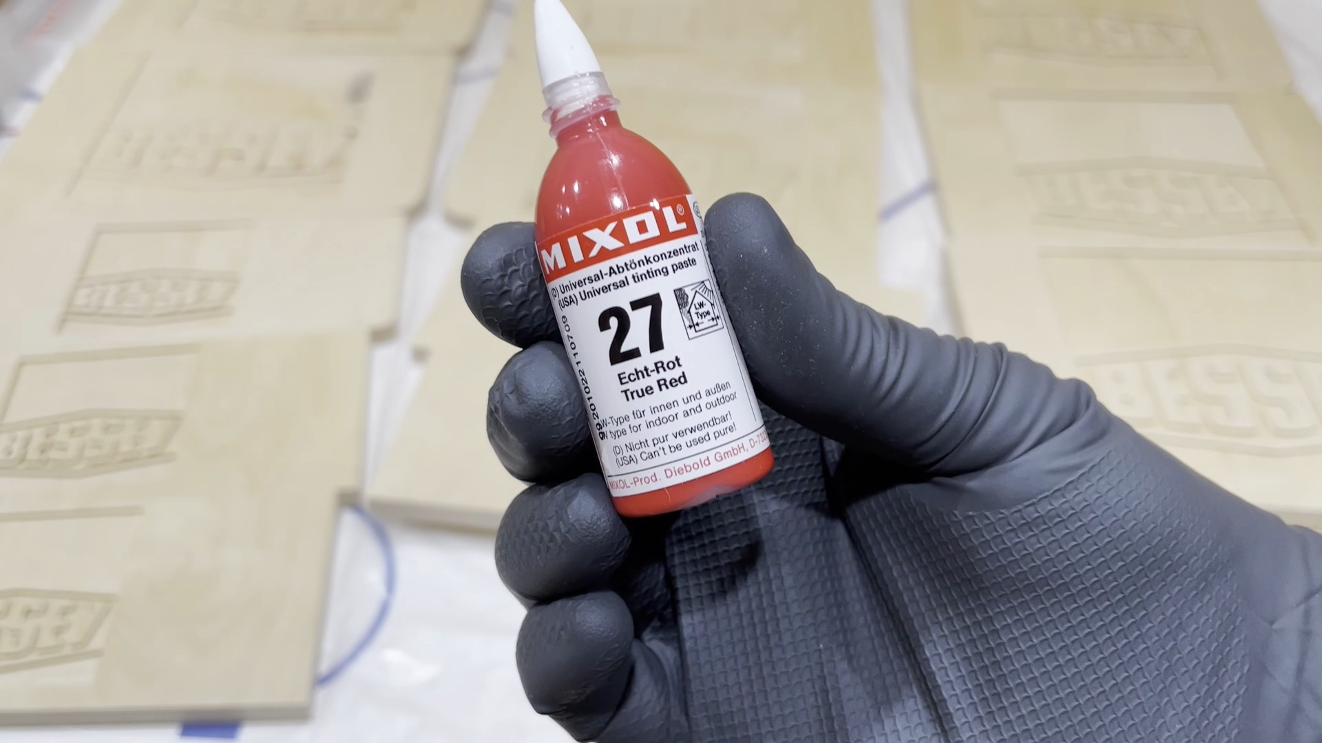
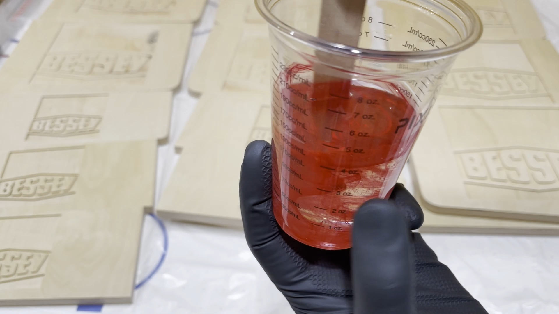
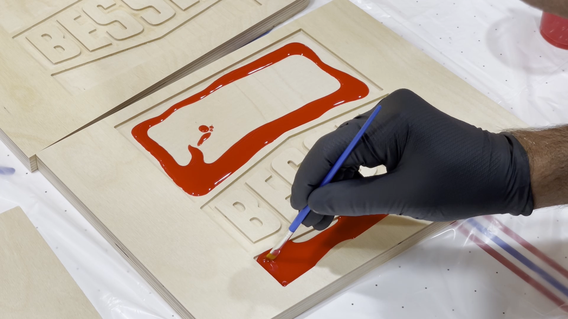
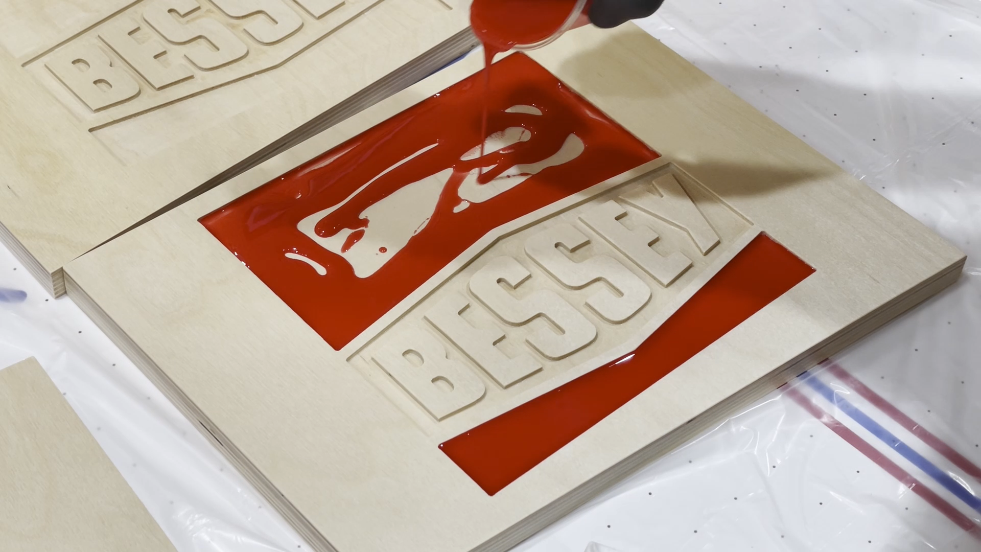

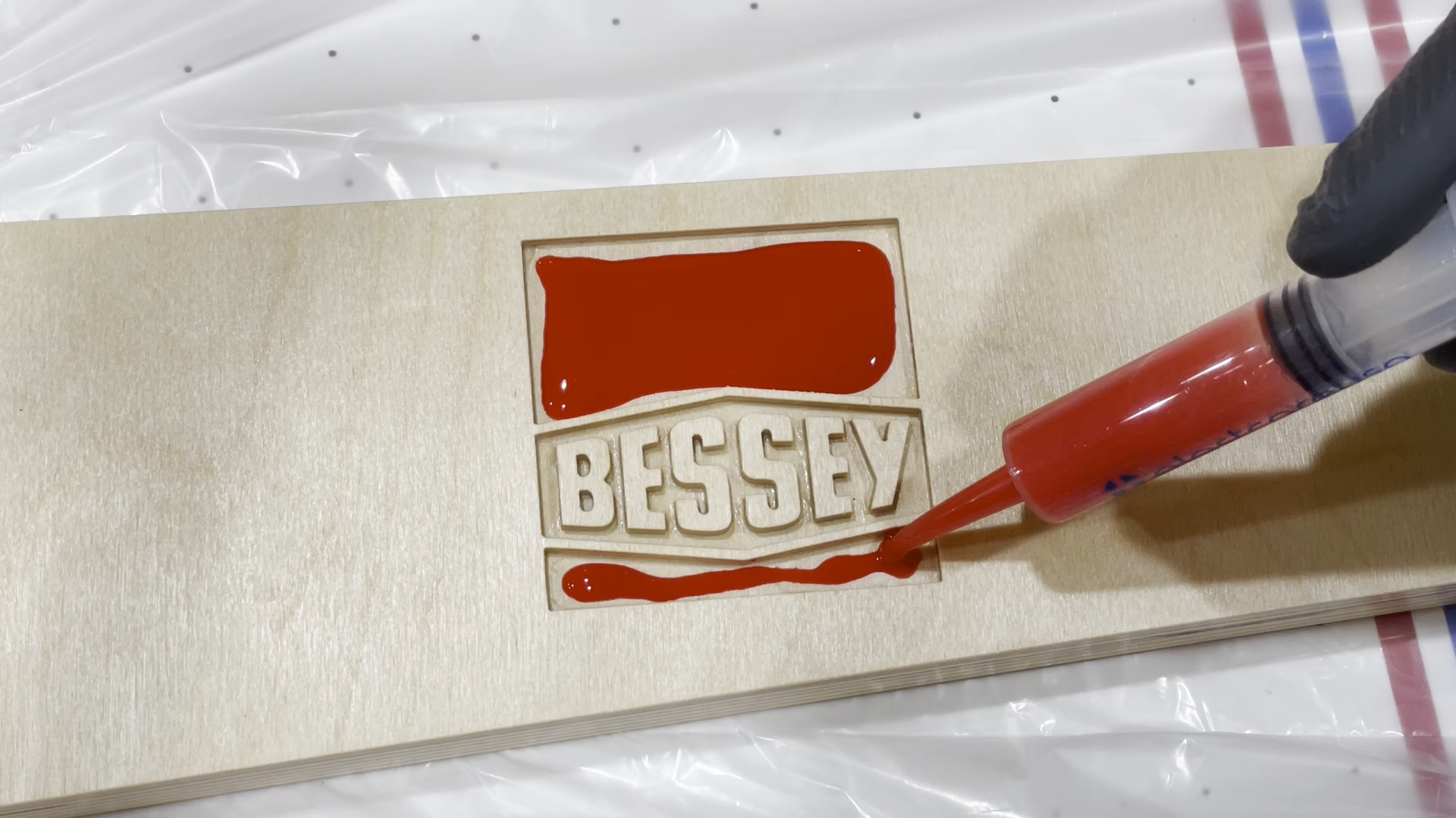
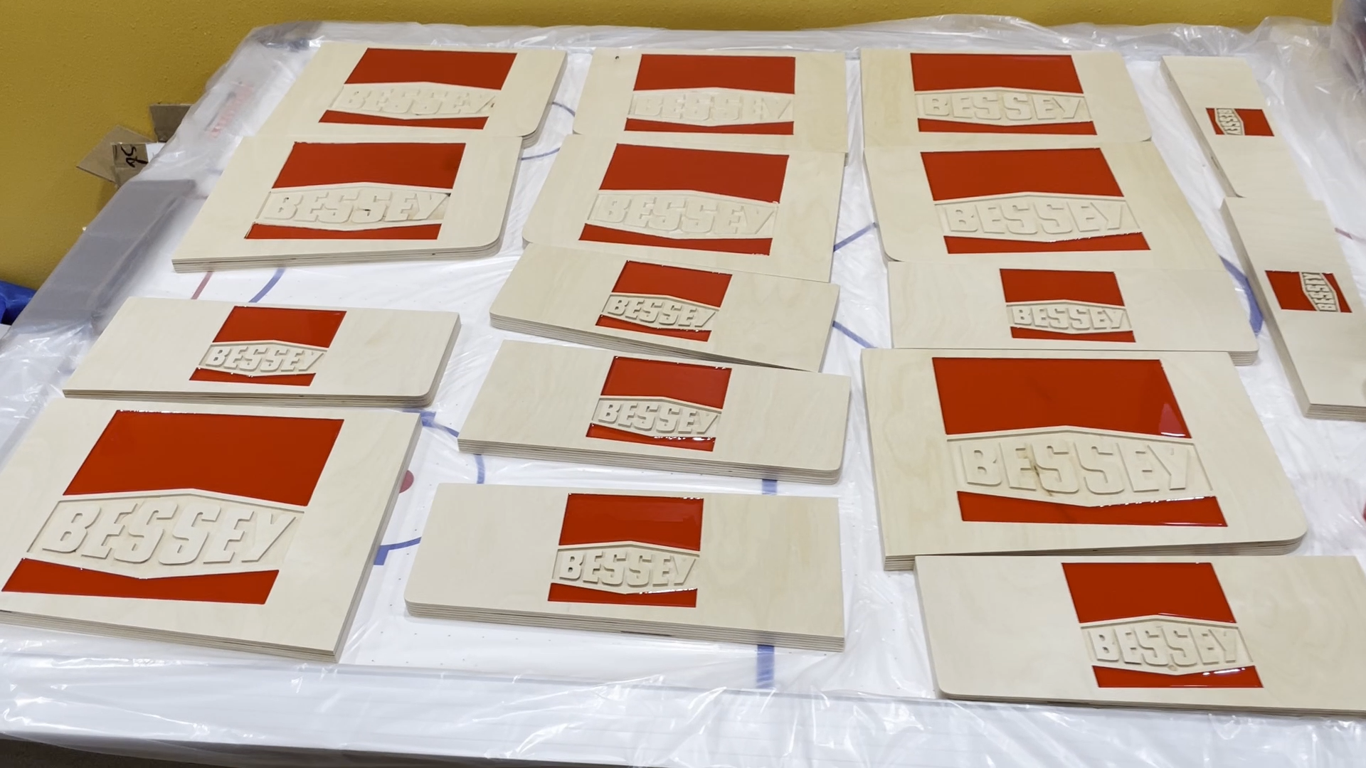
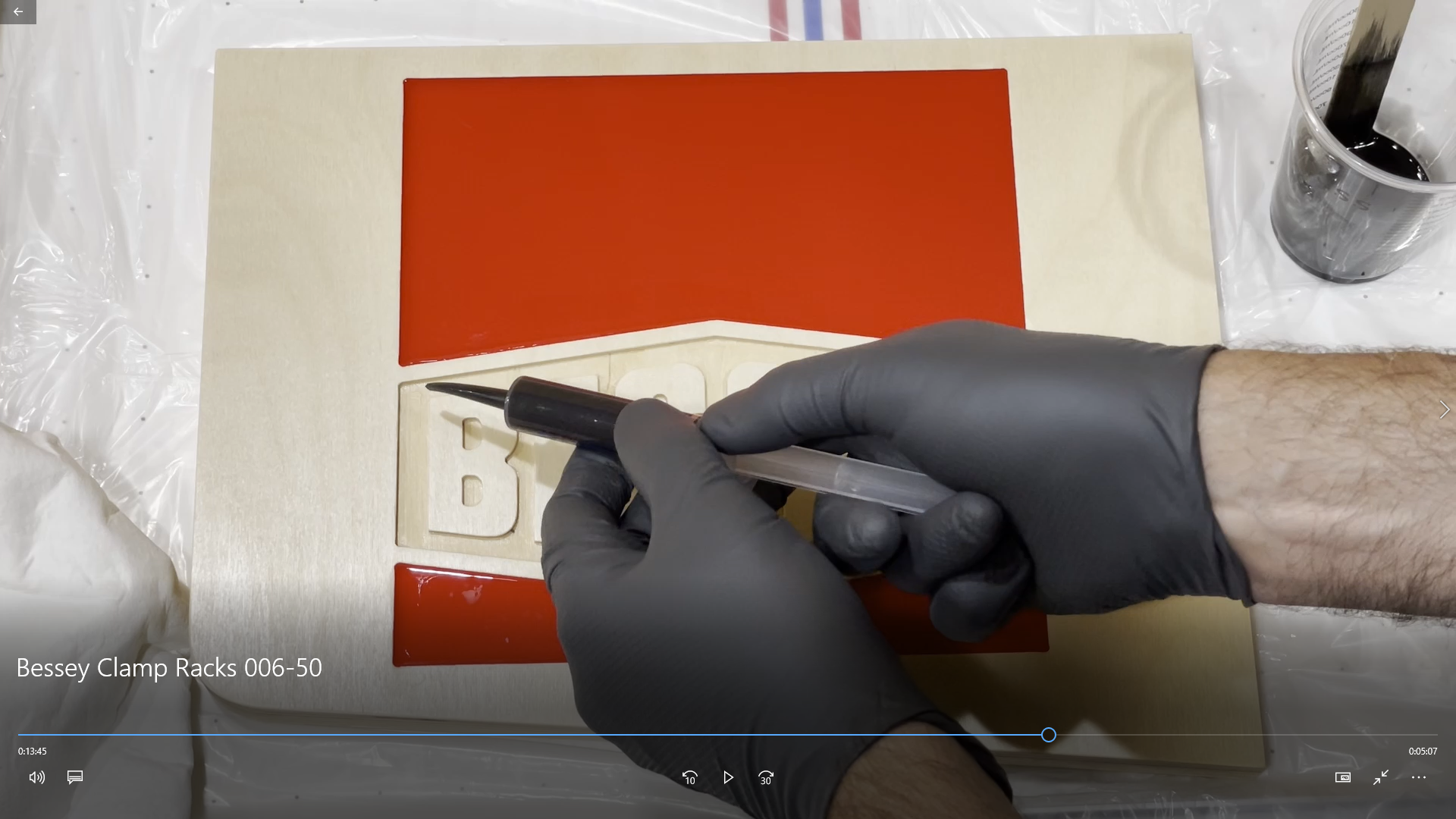
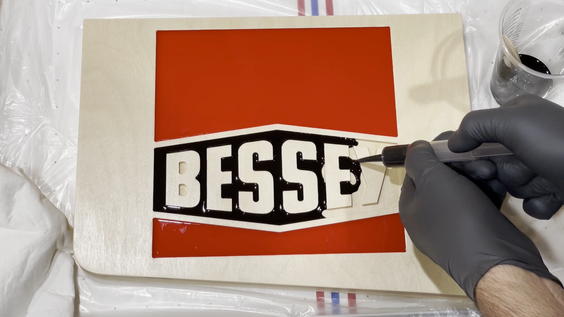
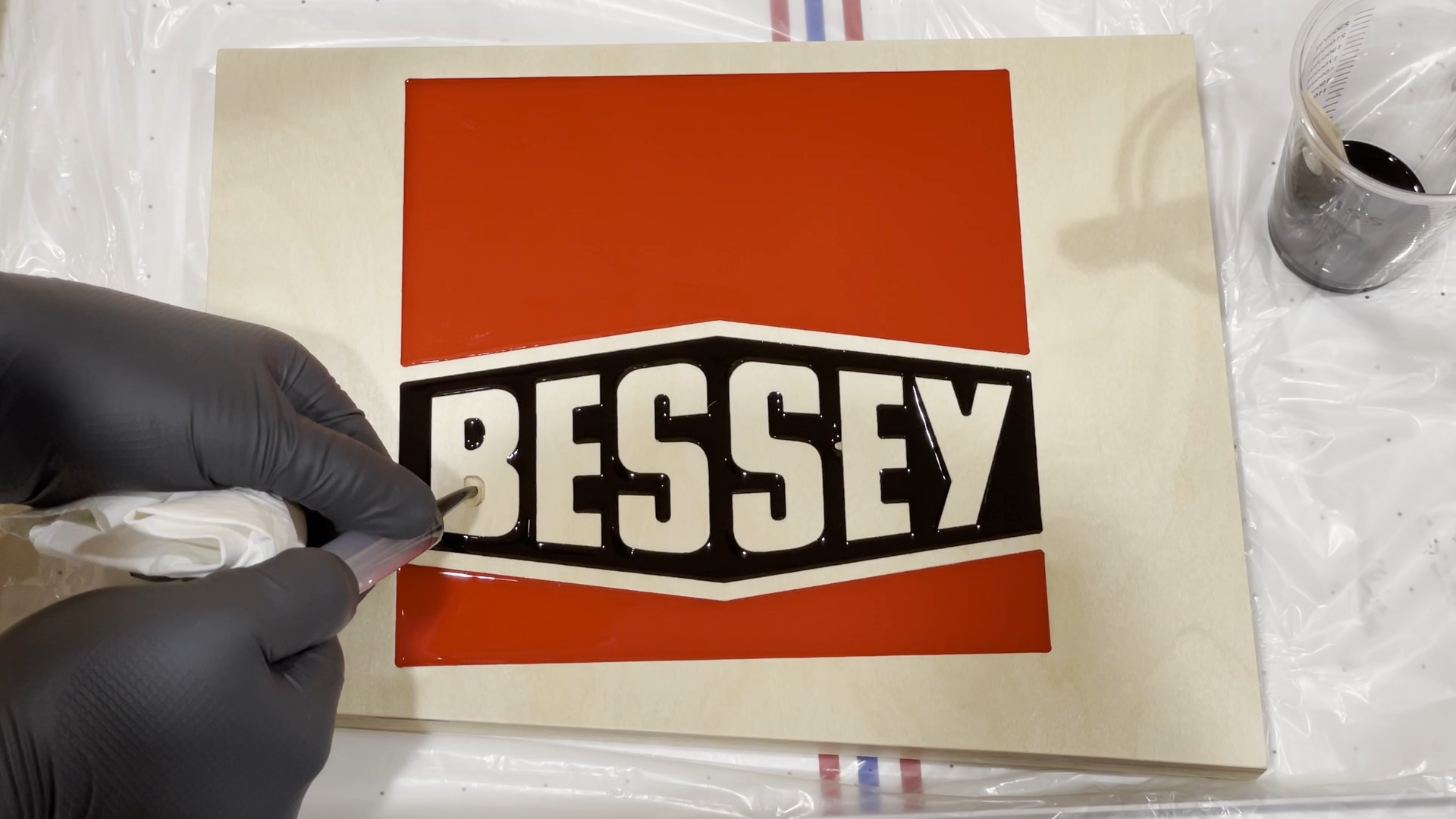
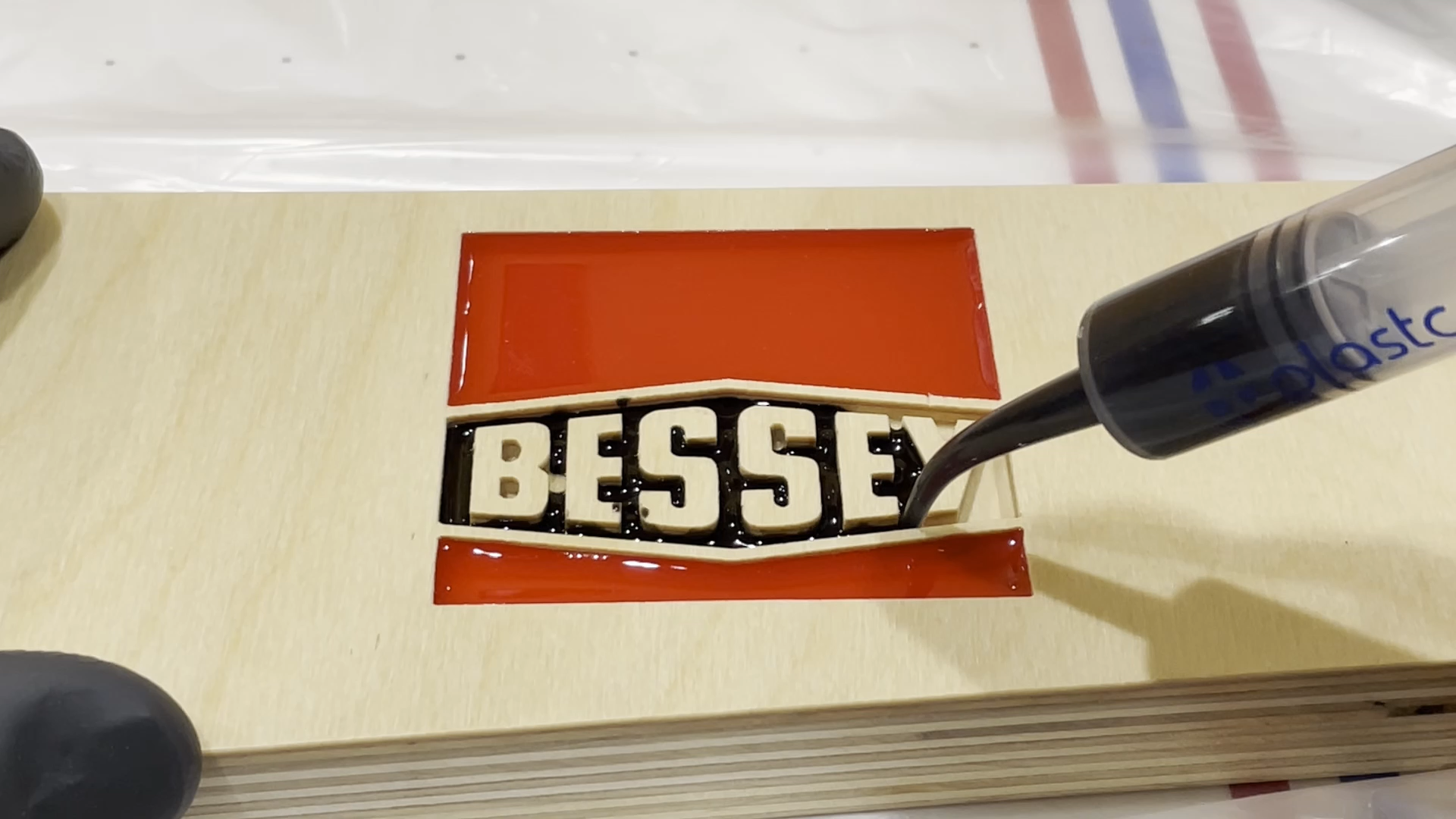
I started the epoxy pouring by the red tinted sections first. I thought these would be easier to pour and would be good practice for the black sections around the lettering.
The red pours used Totalboat High Performance epoxy with medium set speed.
I realized after pouring the red areas that the black tinted areas would work much better if I used Totalboat Deep Pour epoxy. This flows a little better and has a slightly longer working time. The longer working time gives you time to pour several of the clamp rack logos and also allows more air bubble to rise to the surface of the epoxy before the epoxy starts setting up. I did use a torch to help pop some of the epoxy bubbles before it set up.
I recommend only mixing enough epoxy for one or two pieces at a time as it does take a little time to pour the epoxy and work it into the different areas of the logo.
Step 8: Add Back Plate and Cleat
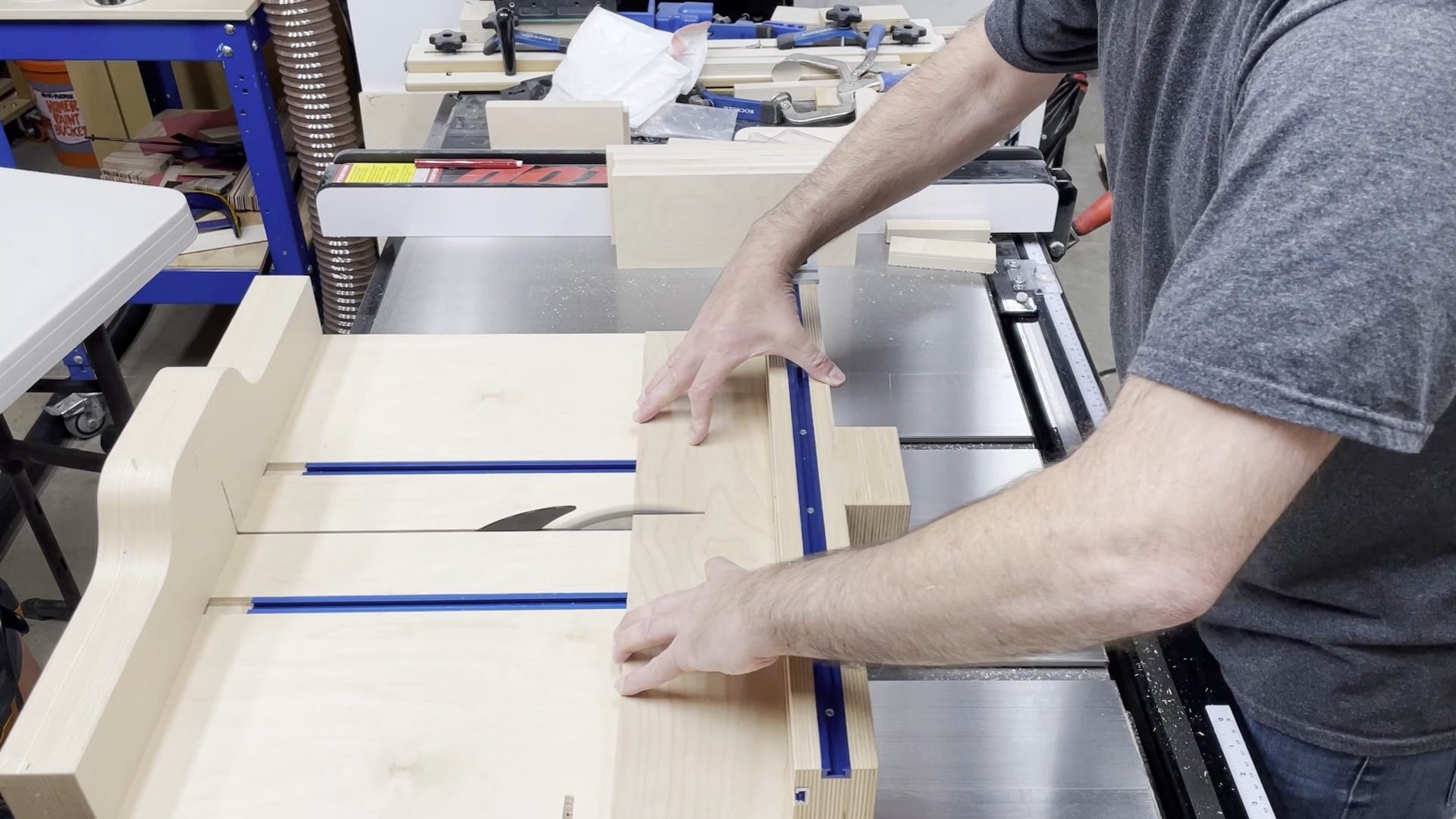
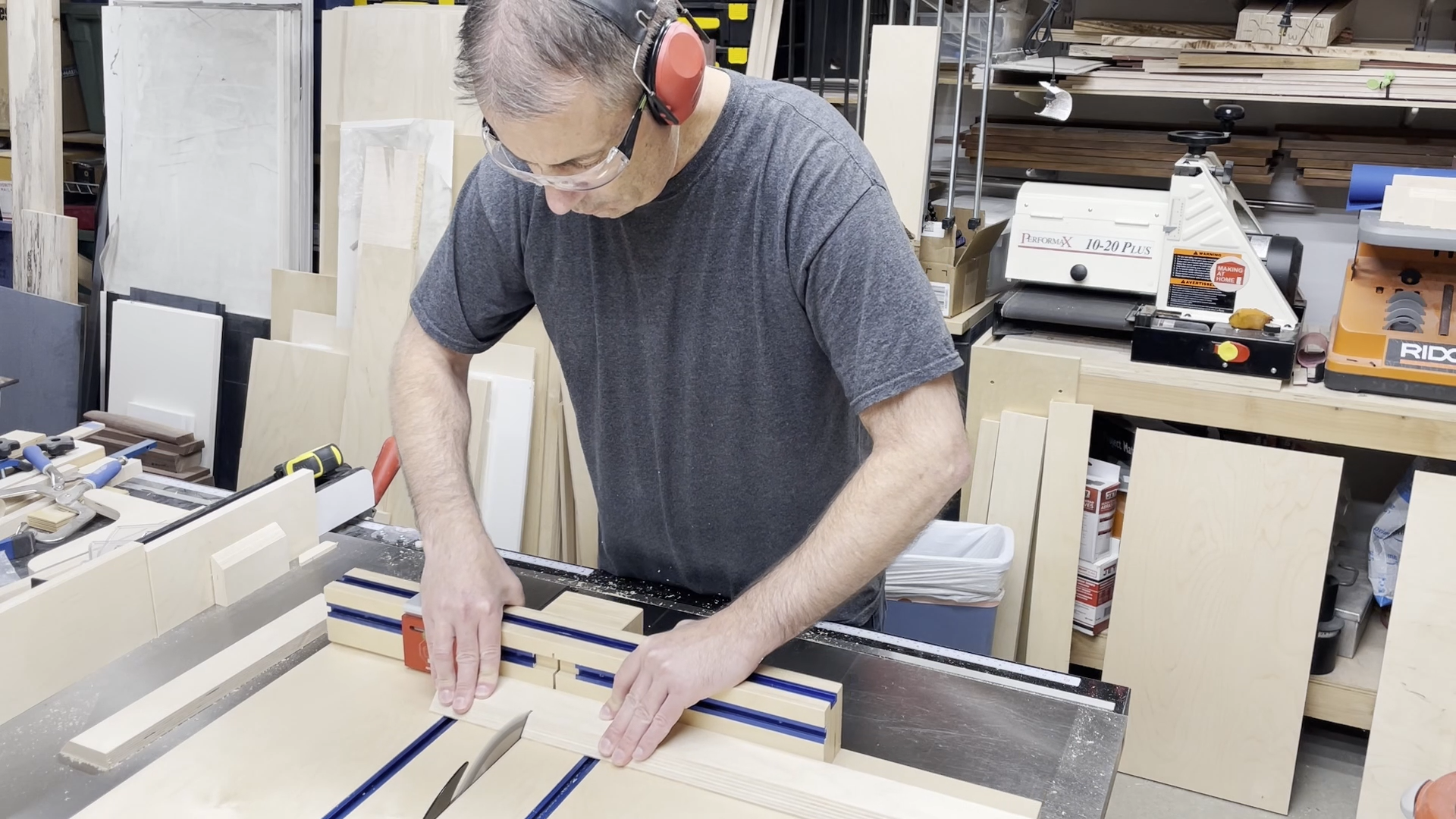
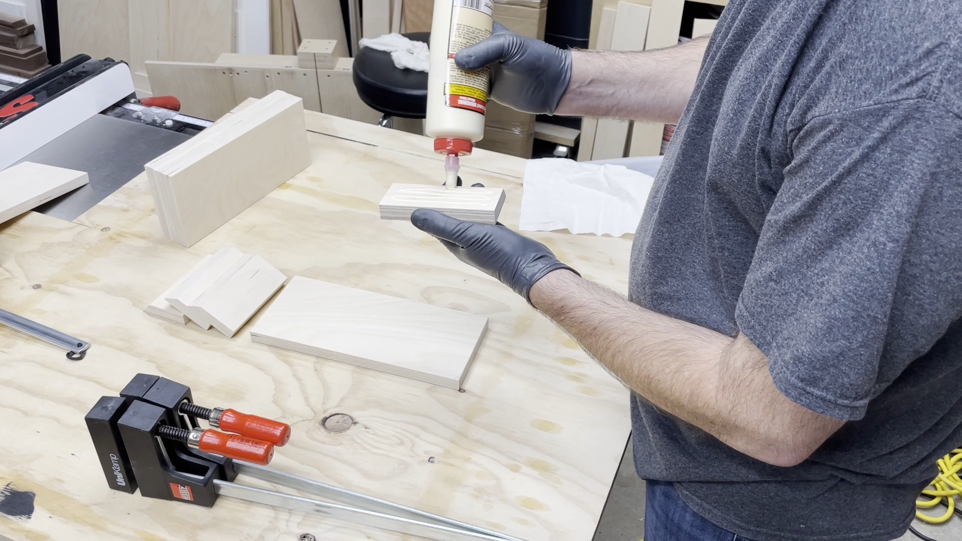
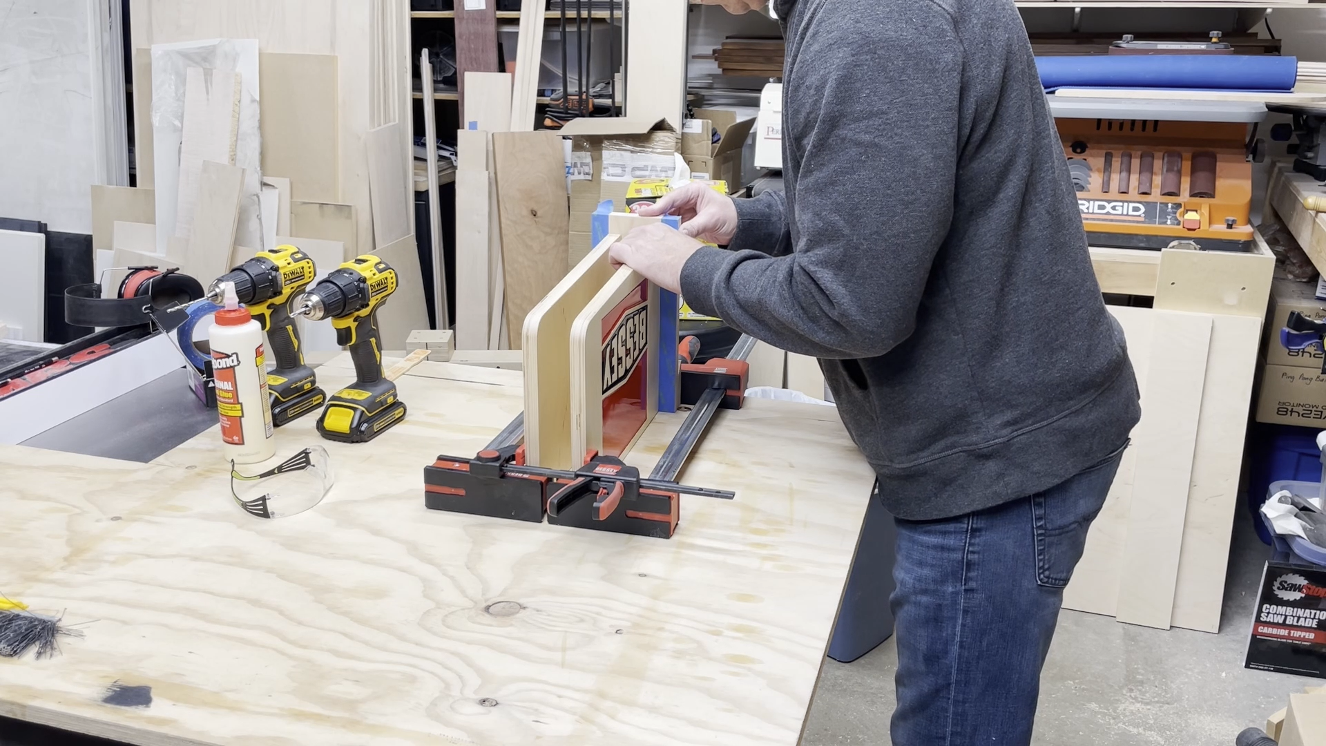
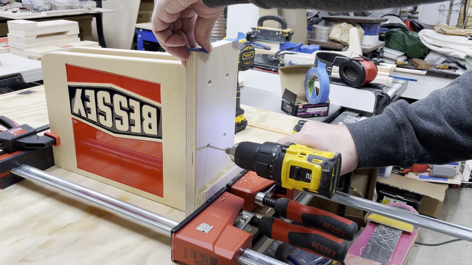
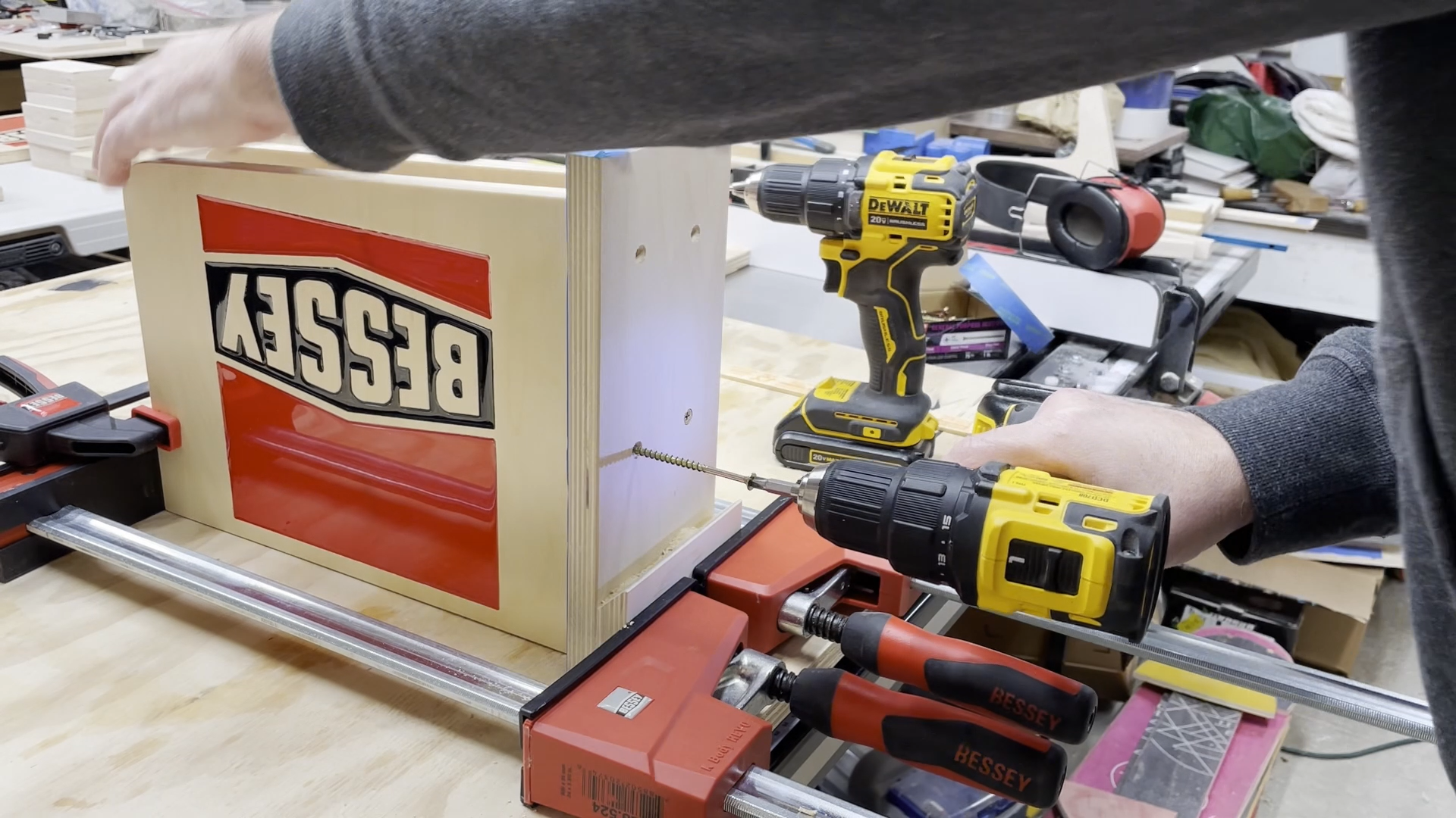
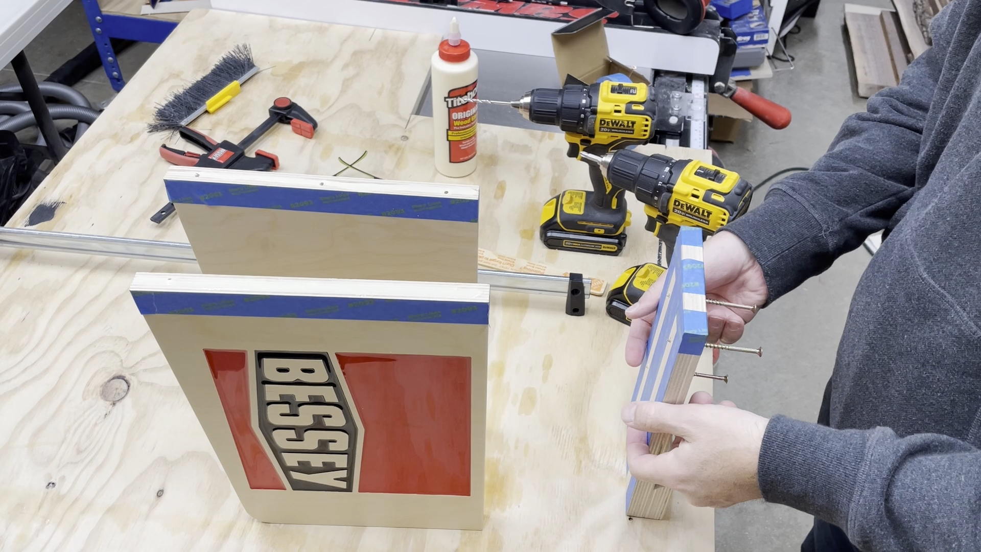
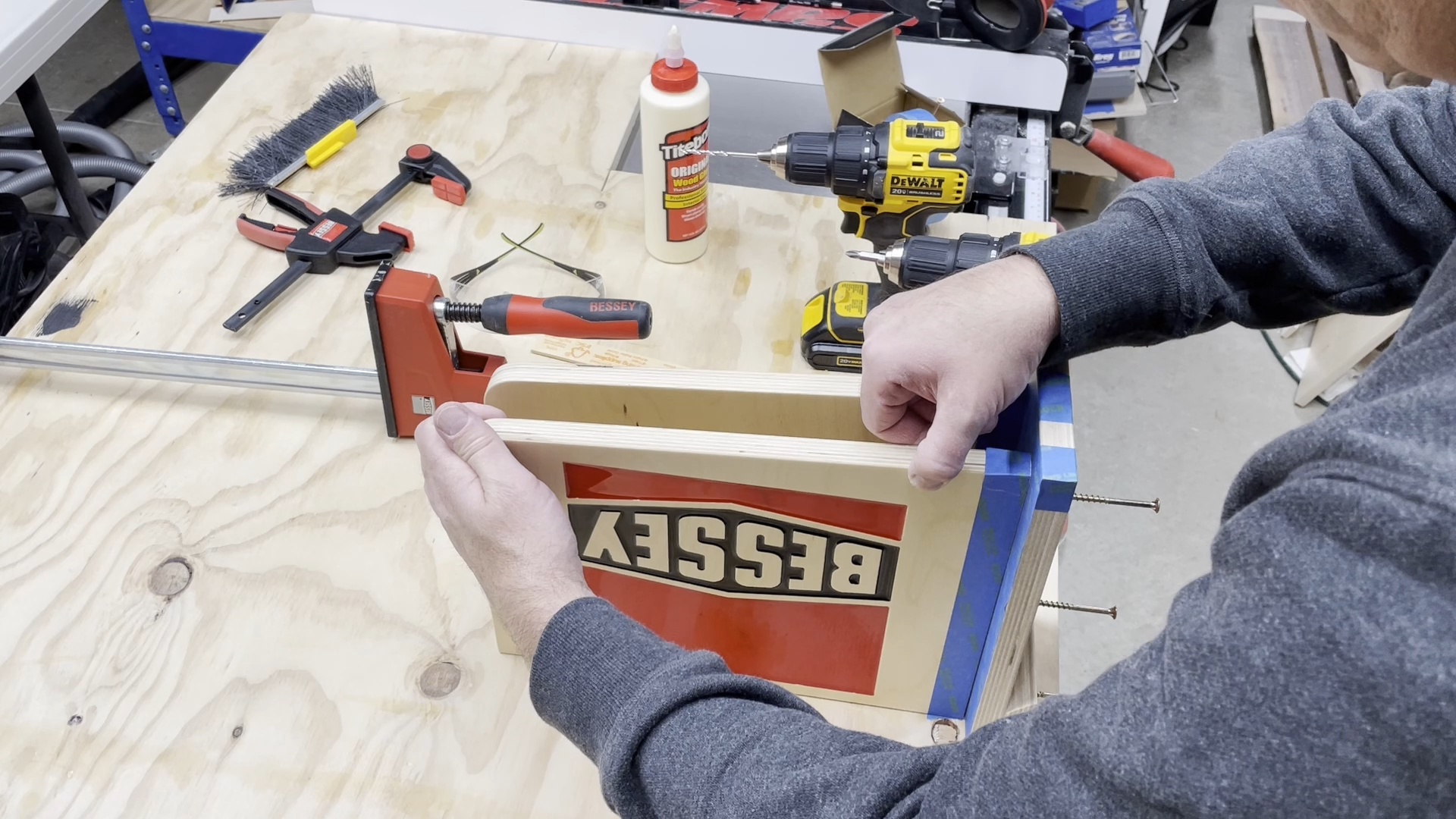
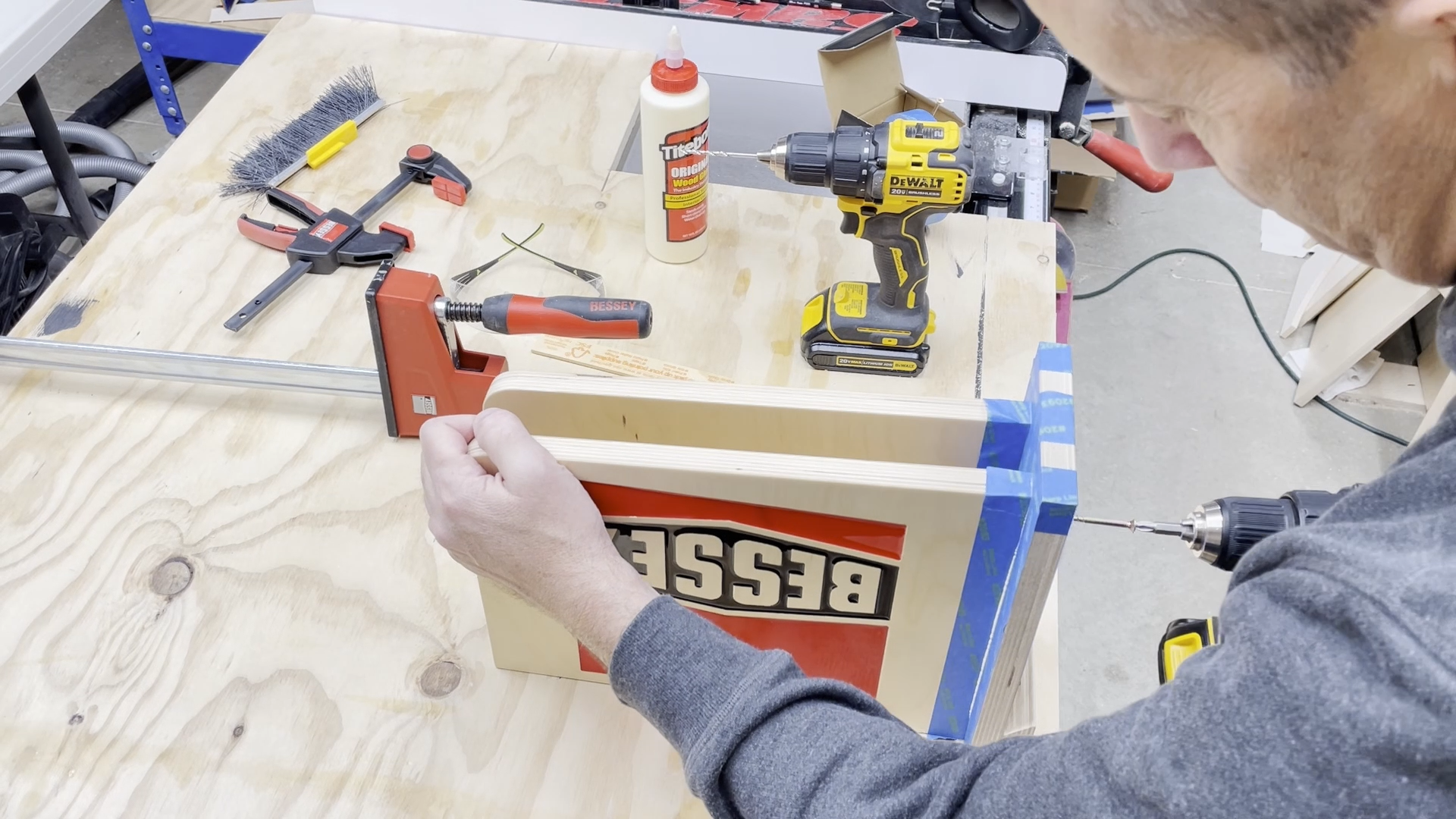
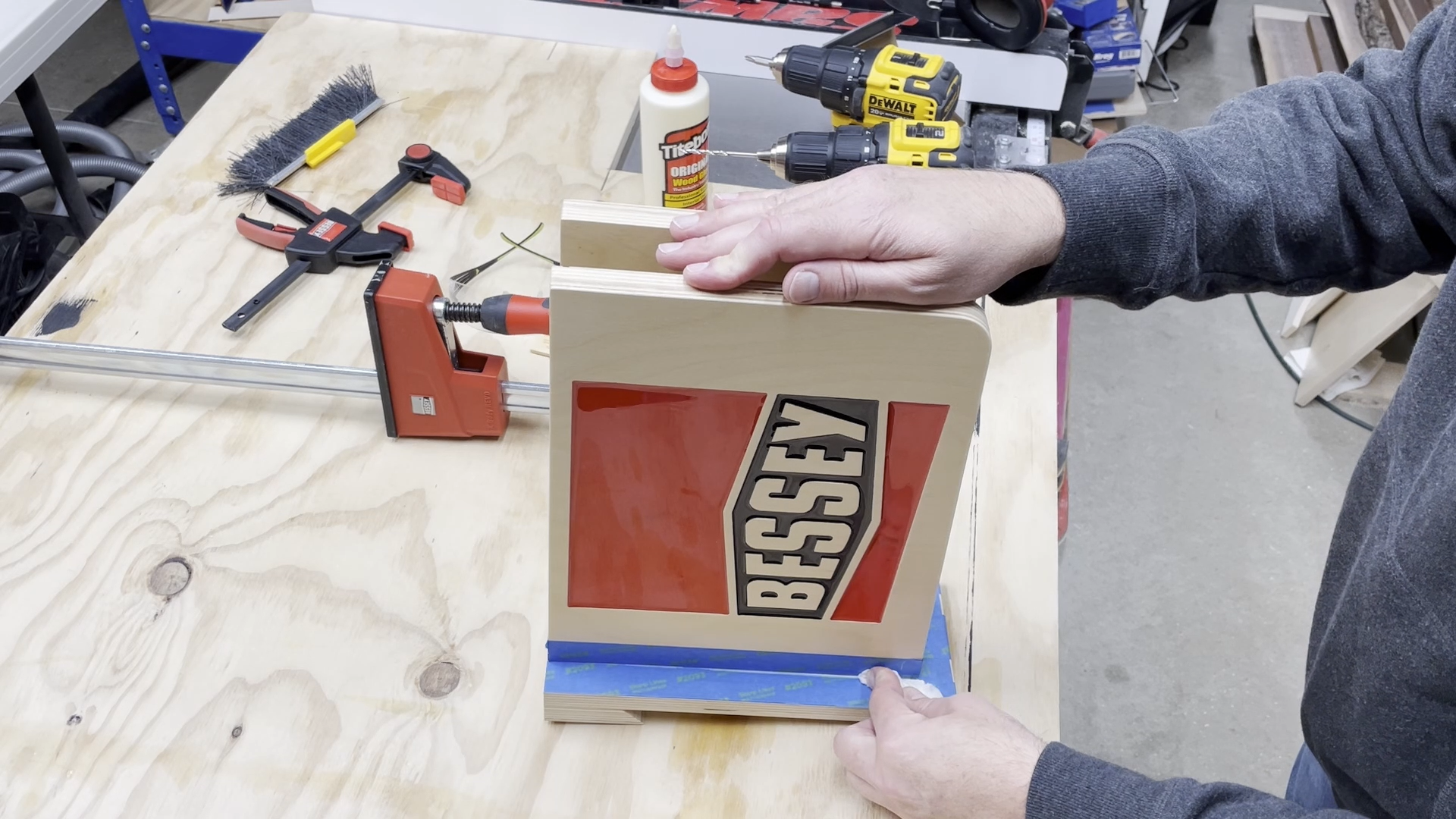
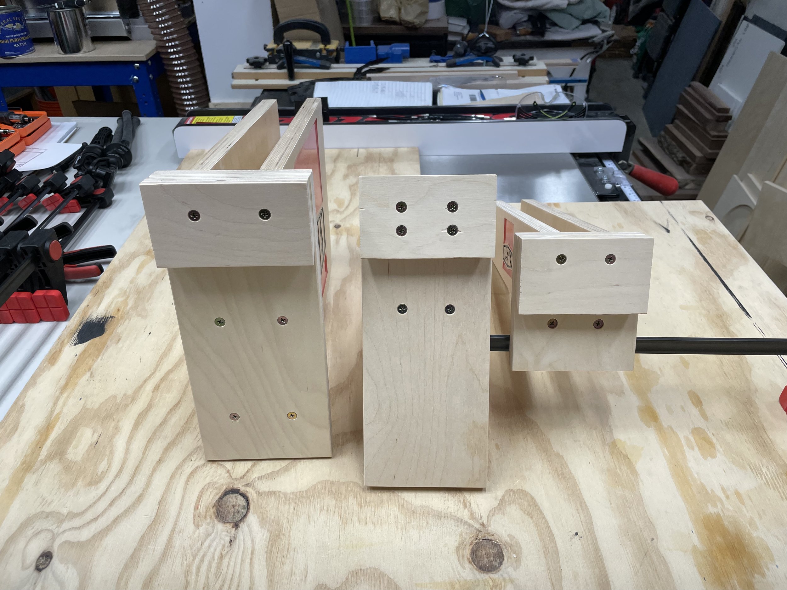
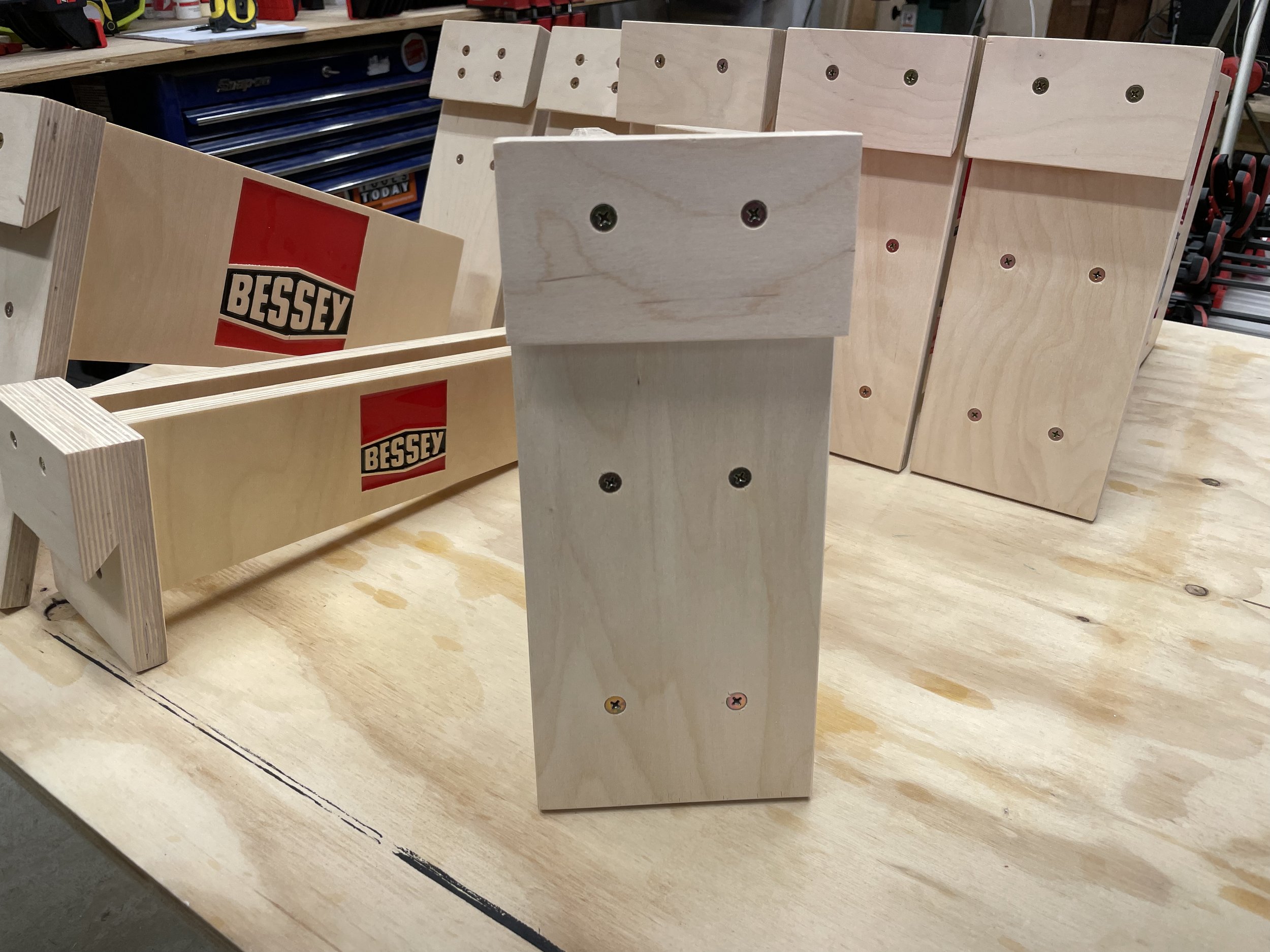
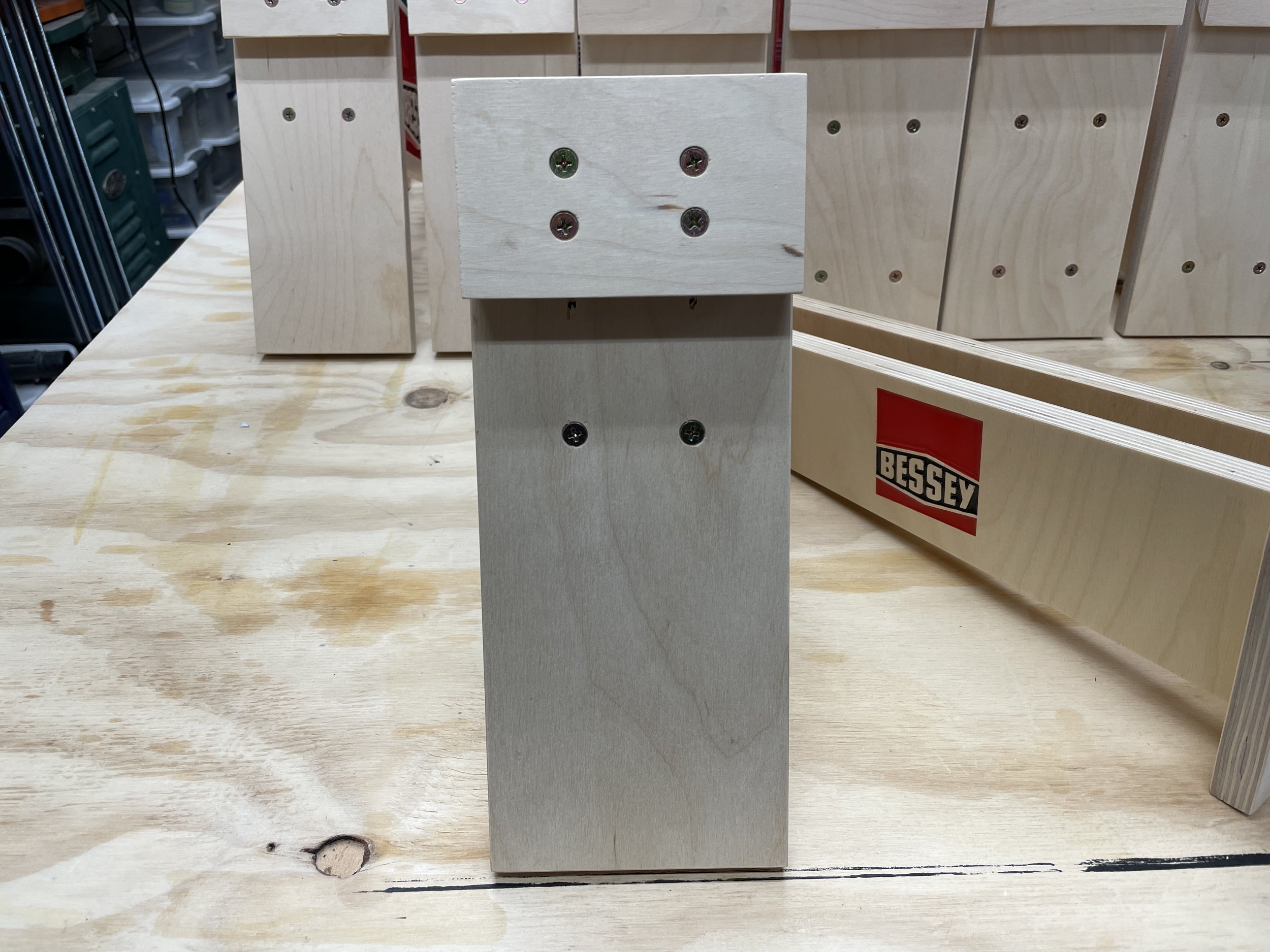
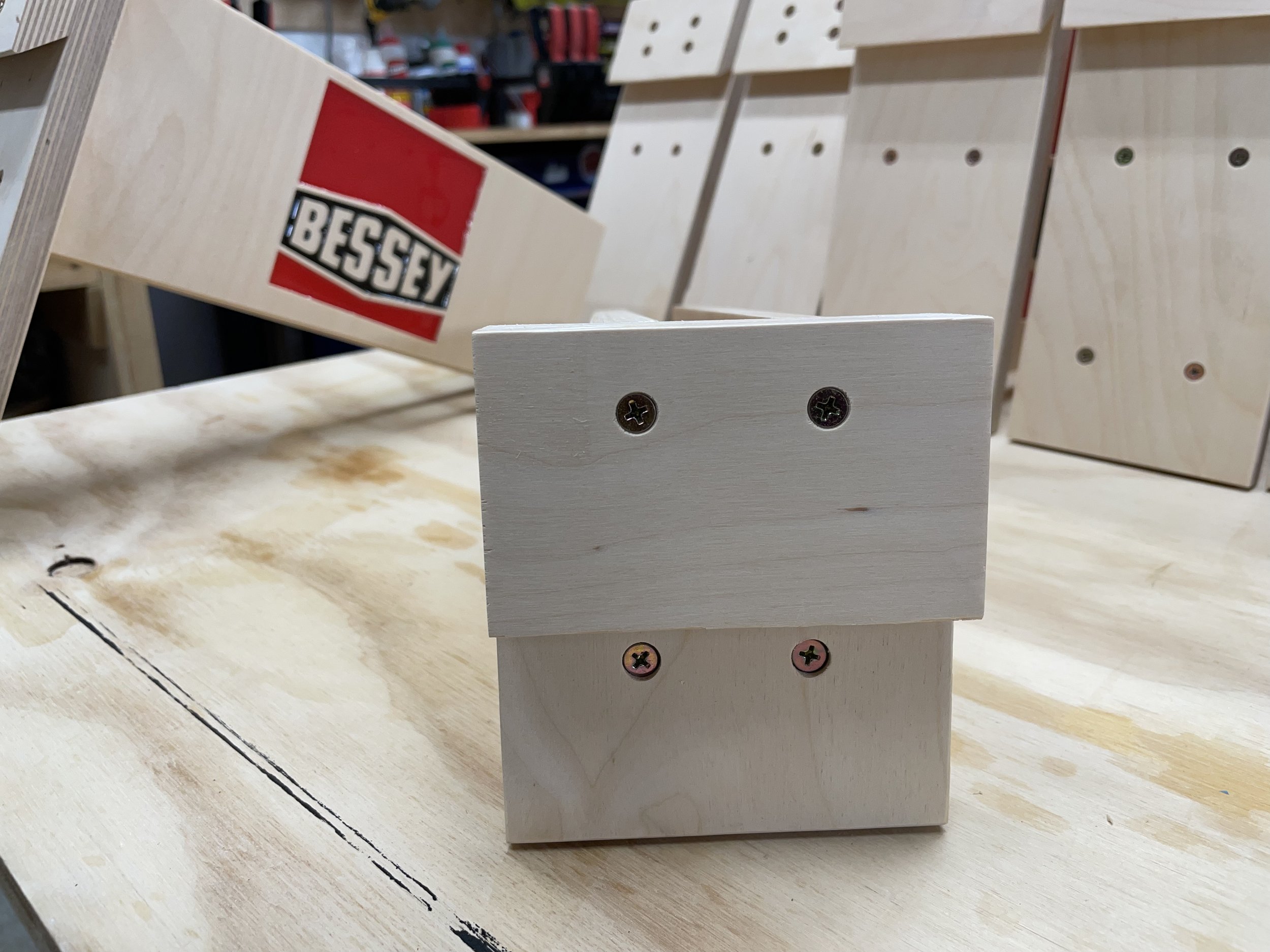
After I gave the last pours of epoxy several days to cure, I cut the rear plates for the racks that will support the side plates and cut short sections of french cleats that are attached to the rear support plates.
The rear support plates for the three different sized clamp racks are as follows:
4.5" Clamp Rack
Size is 4.375" wide x 15" tall x 3/4" thick
From the top of the back piece going down the screws are spaced 3/4" and 3-1/4"
6" Clamp Rack
Size is 4.375" wide x 11" tall x 3/4" thick
From the top of the back piece going down the screws are spaced 1", 1-3/4" and 4-1/2"
12" Clamp Rack
4.75" wide x 11" tall x 3/4" thick
From the top of the back piece going down the screws are spaced 1", 5" and 9"
I glued the strip of french cleat on to the rear support making sure they were nice and square so the racks would sit square on the french cleat wall.
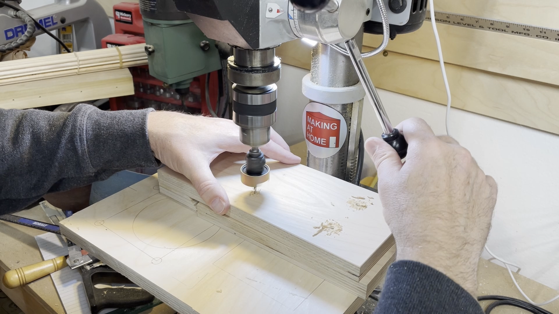
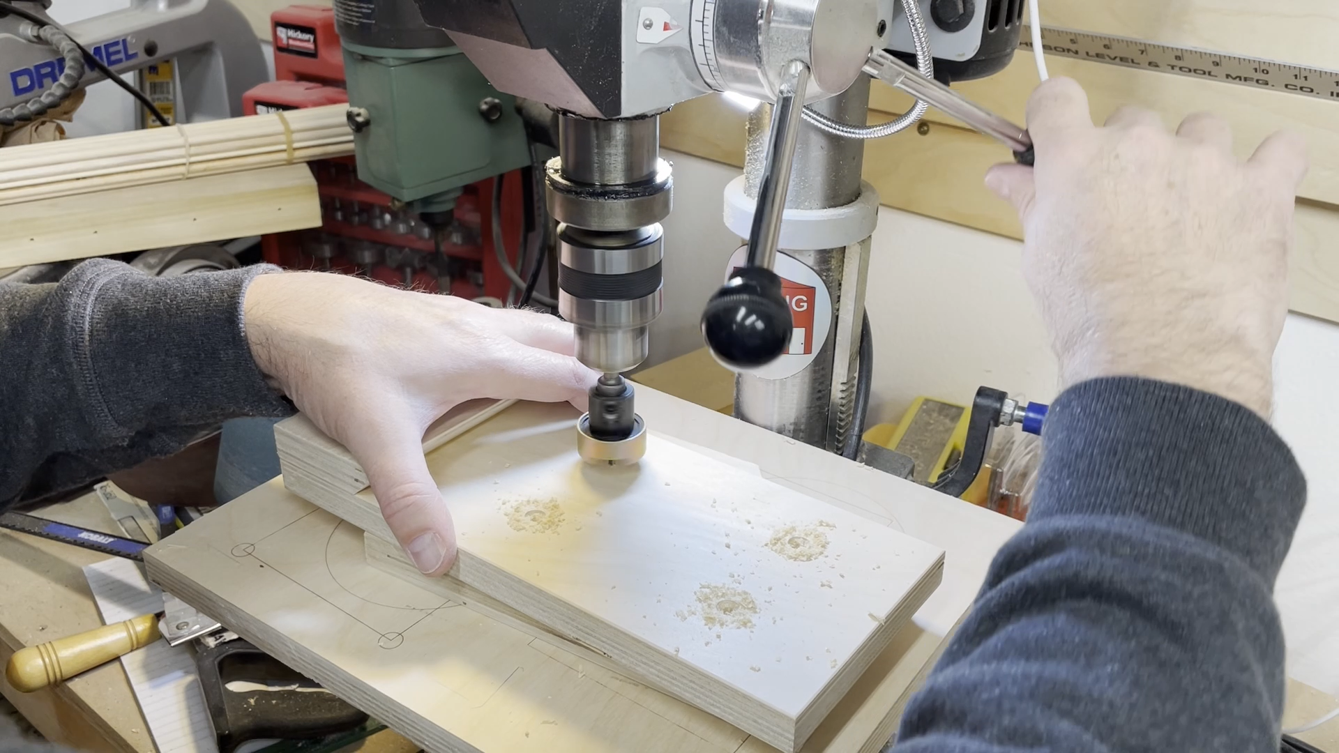
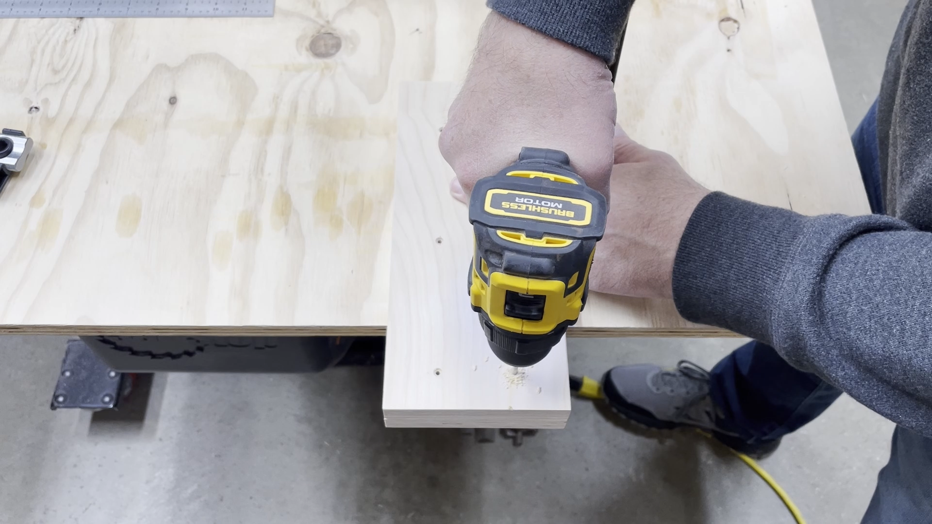
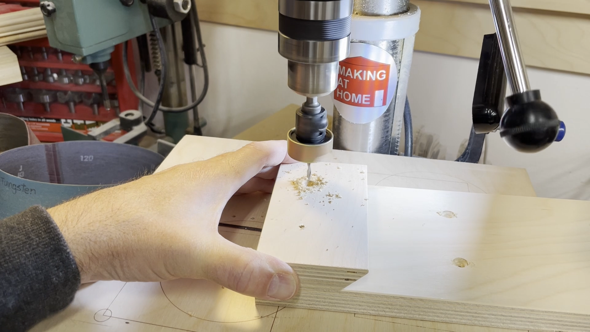
Next it was time to add the side plates with the logos. I pre-marked all of the rear support plates on the front face with the location of the screw holes that will hold the side plates to the rear support. Using a 9/64" drill bit I drilled through the front face of the rear support. I then flipped this piece over and I used the Amana countersink bit to countersink the hole from the back side so the 3" construction screws would sit flush to the back of the rear support.
I added a strip of 1" wide tape down both sides of the face of the rear support. This way I could align the edge of the side plate to the tape and know the sides were 1" in from the edge.
The screw spacing to hold the clamp rack sides to the back piece are as follows:
4.5" Clamp Rack - From the top of the back piece going down the screws are spaced 3/4" and 3-1/4"
6" Clamp Rack - From the top of the back piece going down the screws are spaced 1", 1-3/4" and 4-1/2"
12" Clamp Rack - From the top of the back piece going down the screws are spaced 1", 5" and 9"
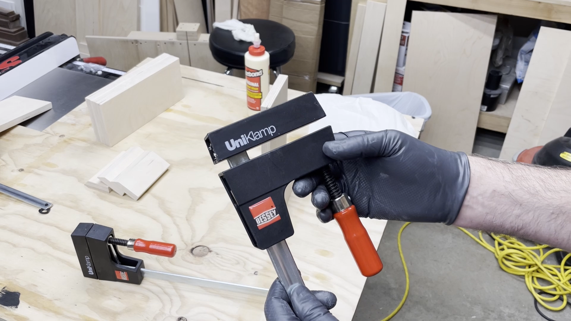
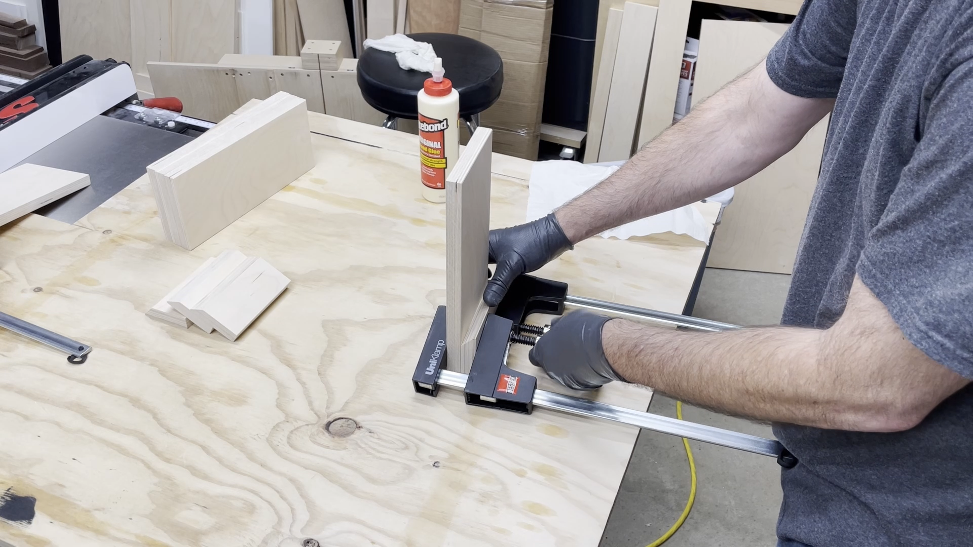
I used the Bessey 12-inch UniKlamp clamps and the 24-inch K-Body parallel clamps to hold the side plates in position while I drilled through the rear support plate and into the rear edge of the side plates. Make sure you keep checking your alignment of the side plates with the tape line to make sure nothing has shifted on you. After you have drilled a hole go ahead and install the 3" construction screw before you drill the next hole location. This will help keep the screw holes in alignment. At this point you can add some more painters take around the area where the side plates attach to the back support. This will help keep glue from getting on exposed areas of the unfinished back piece.
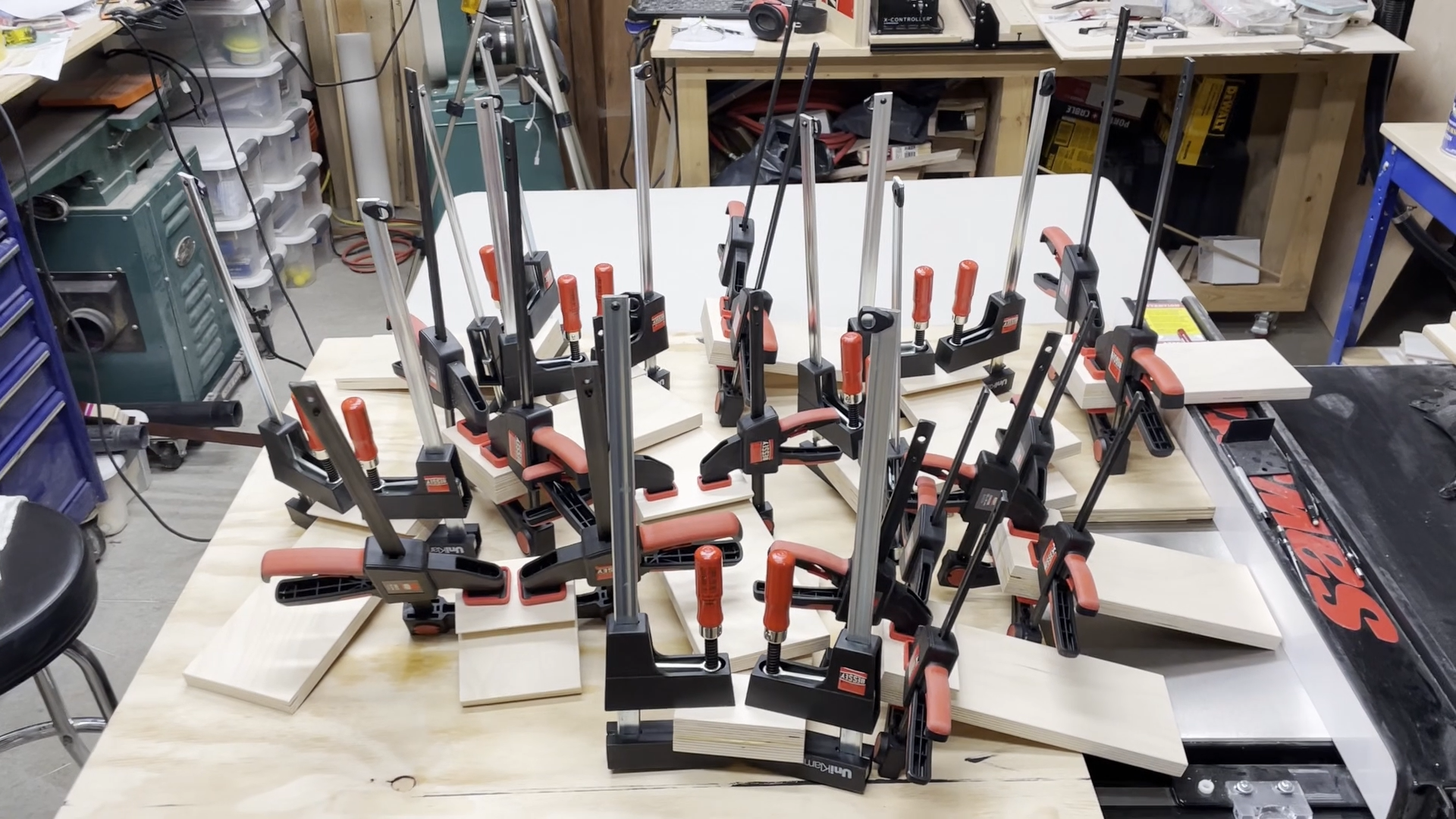
Once you have all of the pieces screwed together and everything fits well, you can remove the screws holding on the side plates, add some wood glue, and then screw them back together. If you added some blue painters take in the last step to mask off the glue areas you can now use a rag to remove the excess glue that has squeezed out.
You can now remove all of the painters tape you had applied to mask off the areas around the side support plates and set the cleat rack out of the way for the glue to dry. A great place for this is on the cleat wall, of course.
Step 9: Hang Racks and Add Clamps
Click here to get the plans on the Inventables web site
Click here to subscribe to my YouTube channel.
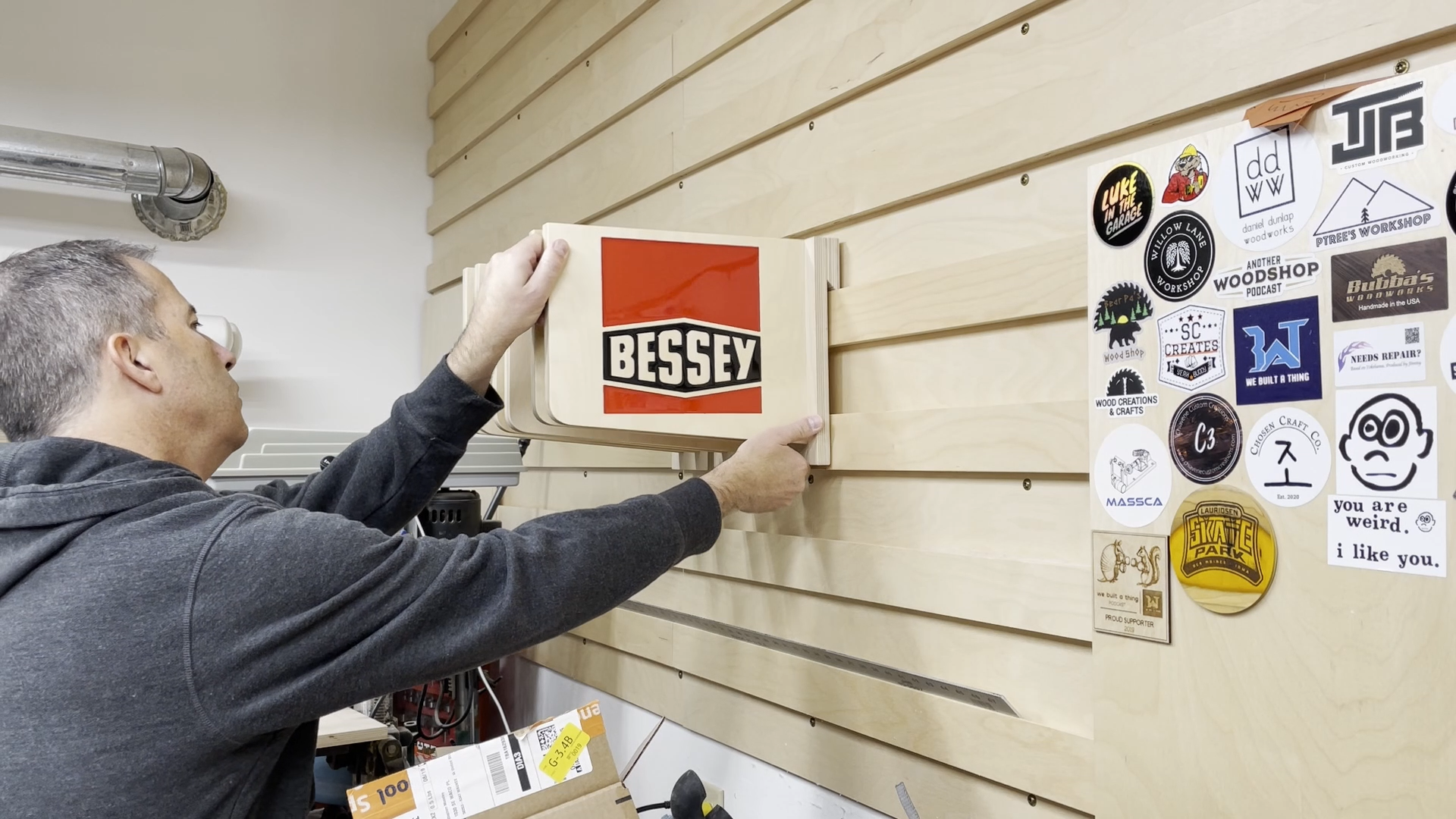
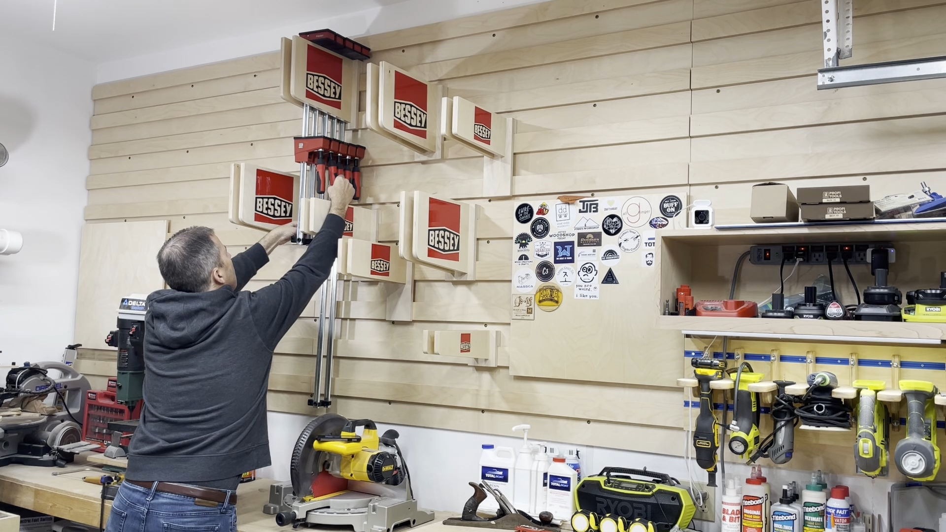
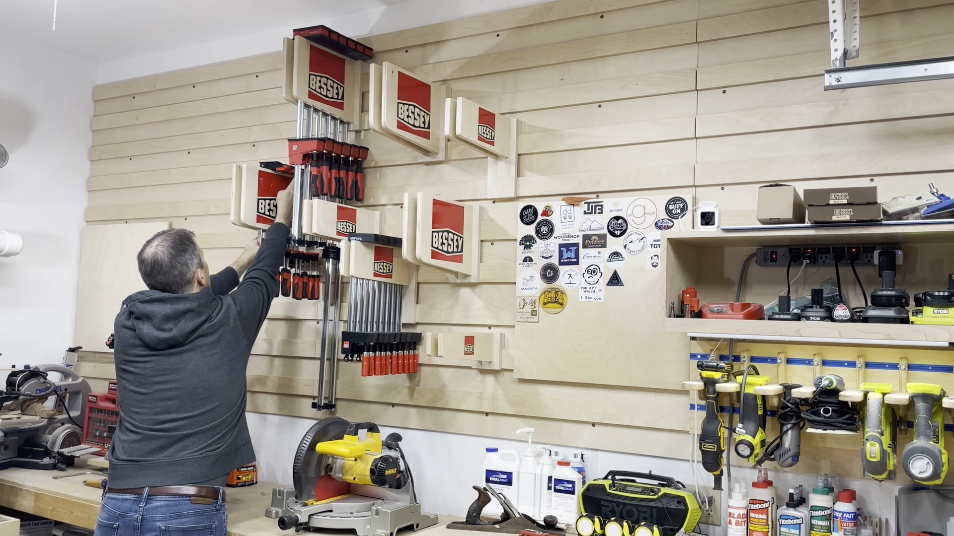
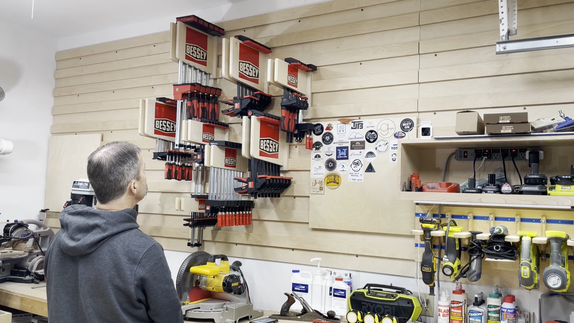
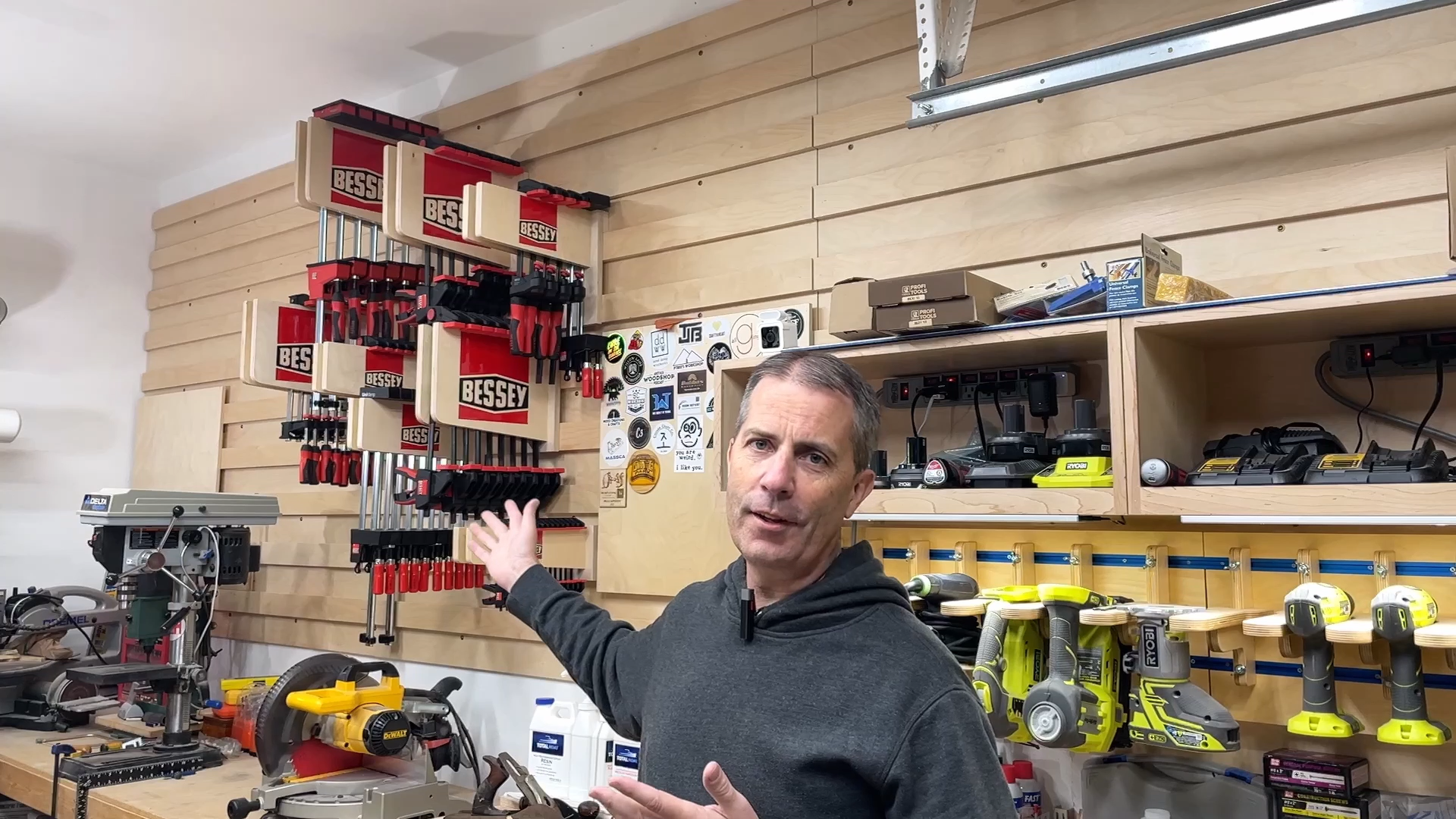
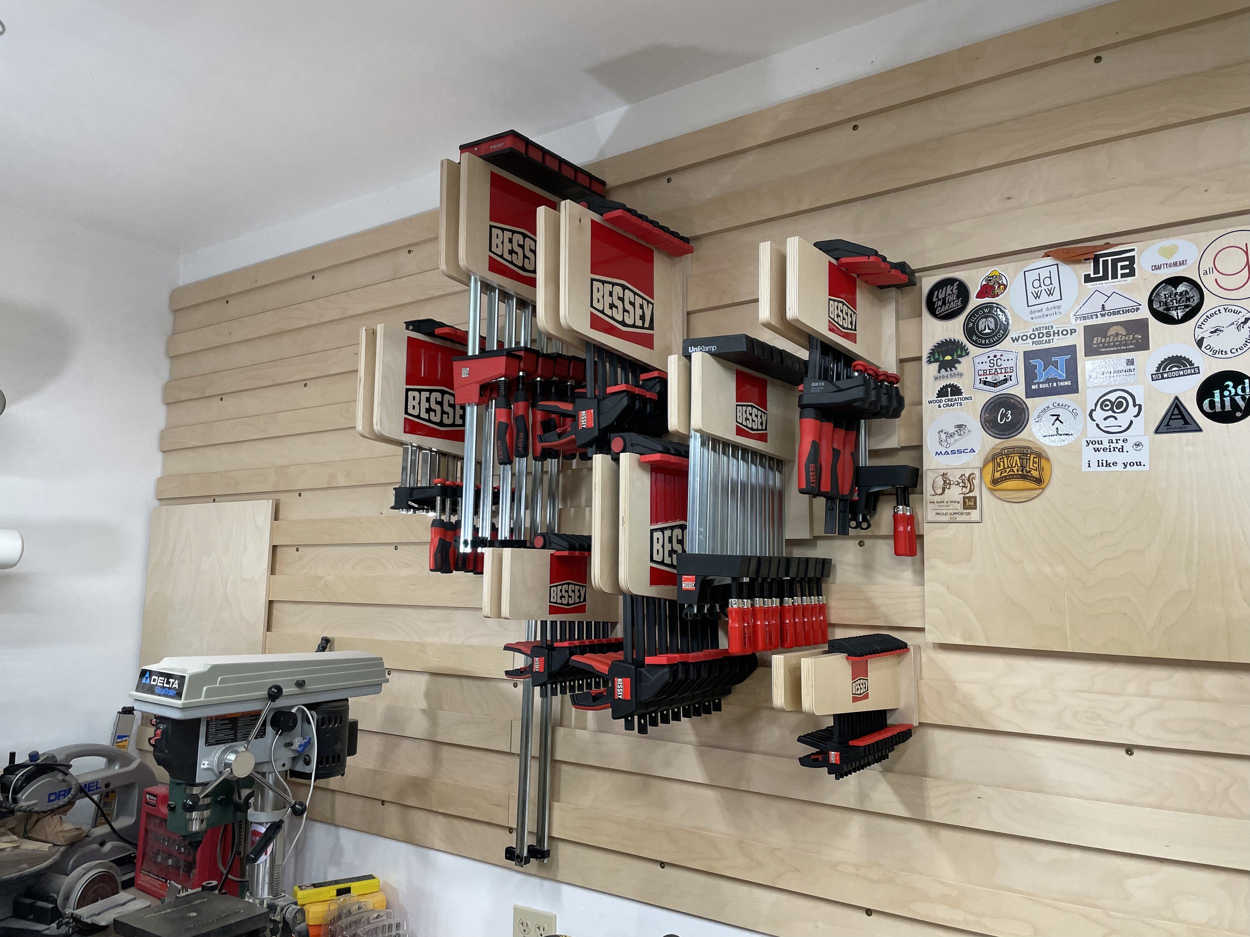
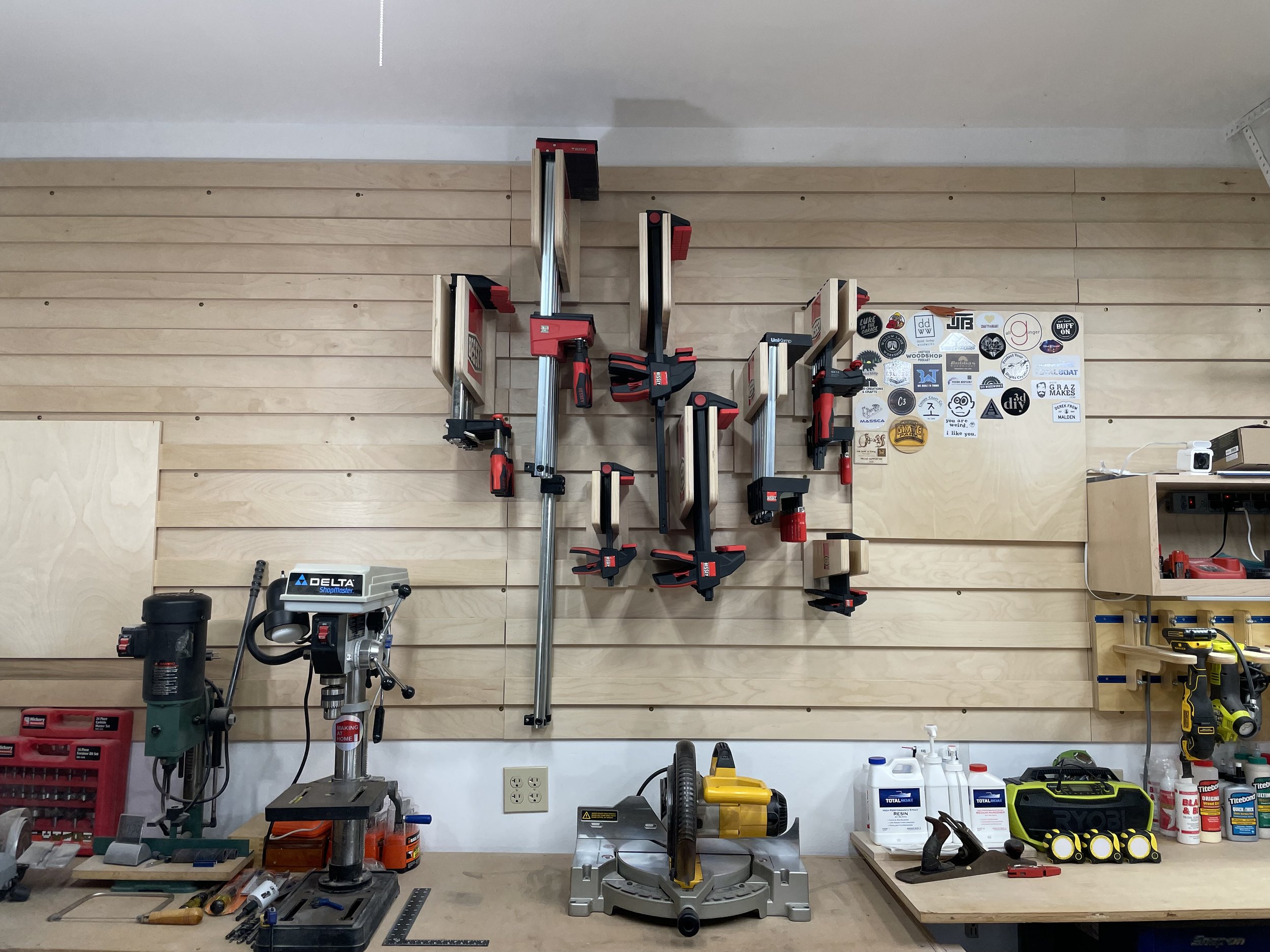
Now that you have an adjustable clamp rack system you will need to move these around on your cleat wall to find the best layout. My cleat wall has cleats every 6" vertically so I have some great flexibility on placement. I recommebr hanging one clamp on each rack and then move those around to where you like where they are and there is no conflict. Then you can add the rest of the clamps to each rack. Trying to move them around when they are fully loaded can be a challenge or a little dangerous.
If you don’t have a cleat wall then you can either make a couple long cleats to attached to your wall and then hang the racks or build these without the cleats on the back and then screw them to your wall.
I hope this project helps you get your shop organized. I have a few more items for the cleat wall I am currently working on so check back often and make sure you subscribe to my YouTube channel.
A big thank you to Bessey Tools for providing some of the clamps used in this project.
